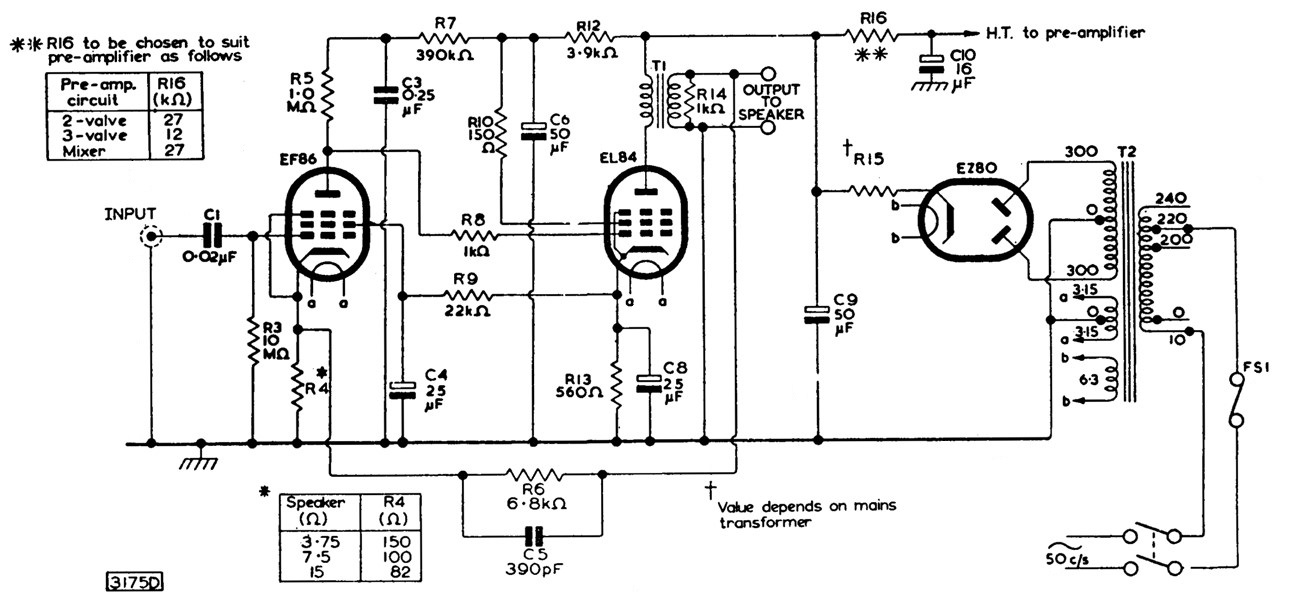
Mullard 3-3 is a quite popular 3 W electron tube amplifier introduced by Mullard Ltd ↗ in 1955. A schematic and the design details of this amplifier are available in the book “Circuits for Audio Amplifiers” by Mullard Limited 1959 and in the book “Hi-Fi Amplifier Circuits” by E. Rodenhuis 1960 Philips Technical Library, and also in the National Valve Museum website article ↗. The amplifier uses three vacuum tubes: an EF86, an EL84 and an EZ80.
The power output is ample for home use with a loud speaker of ordinary sensitivity and is generally agreed that a higher output is not normally required. The model 1955 (Mullard 3-3) is ideally suited to applications in the average home.
An unusual DC-coupled stages tube amplifier
Only two stages are used and the amplifying stage EF86 is DC-coupled to the single valve output stage EL84. The control grid of EL84 is at the same potential as the anode of EF86 via R8, so the cathode potential of EL84 is about 30 volts above ground. This is a suitable value for the screen grid potential of EF86 via R9, but the most important feature of this strange and clever DC-coupling is a DC negative feedback (NFB) system from cathode of EL84 to screen grid of EF86. It works together with the AC negative feedback from the output of the audio transformer to the cathode of EF86. These improvements enhance the flatness of the frequency response and also reduce harmonic and waveform distortion, as well hum and noise.
The EF86 in the voltage-amplifying stage is used under conditions approaching those of starvation operation, 20 V anode and 0,21 mA. The voltages and currents are very much lower than normally. Instead of using a cathode self-bias the tube bias is obtained by means of a hight value grid leak resistor (10 MΩ). With a high value of anode load resistance (1 MΩ) and reduced values of anode and screen-grid voltages, the gain of the stage is raised two or three times above that obtained under normal operating conditions.
British Broadcasting Corporation
This Mullard 3-3 circuit, with some minor changes, was used by the UK BBC for their Loudspeaker Amplifier AM8/2 and AM8/2A on amplifiers with serial numbers 101 to 185. Loudspeaker Amplifier AM8/2 forms part of the General-Purpose Loudspeaker LS/1 described in Instruction S.8, and is mounted in the amplifier compartment at the bottom of the loudspeaker cabinet.
Its performance and certain other features are specified by the BBC but otherwise its design and construction are left to the manufacturer. We can see the document in the Recollections of BBC engineering from 1922 to 1997 at BBCeng.info ↗.
The project
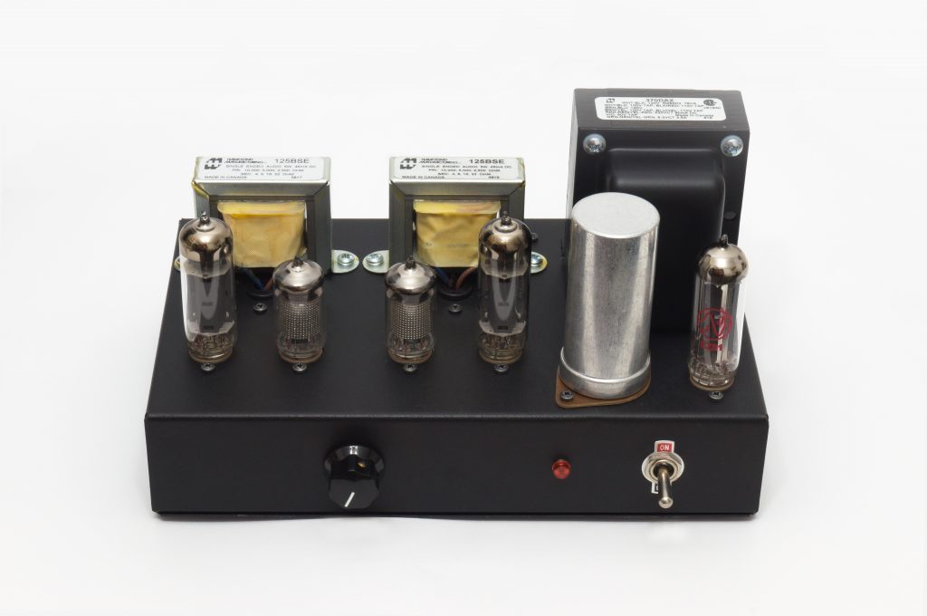
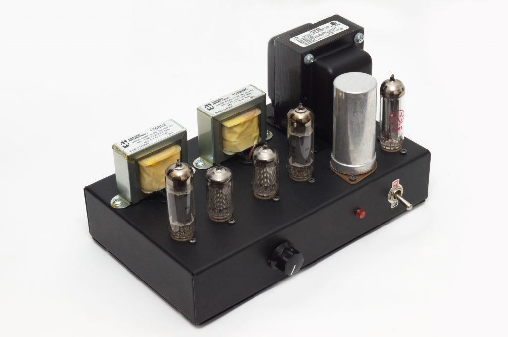
In this project, I decided to construct a quality tube amplifier, while being as electrically similar as possible to the original Mullard 3-3 amplifier, in stereo version. Thanks to their small size the amplifier only requires a little space: 25.4 x 19.2 x 13.3 cm (10 x 7.56 x 5.24 in).
This goal has been achieved via:
- The use of high-quality parts from premium brands: resistors, capacitors, terminals, sockets, fuseholders, switches, connectors and transformers. I have avoided cheap counterparts.
- Drilling and milling a beautiful strong black steel chassis.
- Employing electronic parts as similar as possible to those used in the year 1955, including carbon composite resistors and a can type multi-sectioned electrolytic filter capacitor.
- Avoiding the use of semiconductors, LED lights or printed circuits. The wiring is meticulously point-to-point ↗ hand made.
To simplify the build, I chose to construct the amplifier as a version without tone controls. This was a practical decision intended to make the circuit easier to assemble.
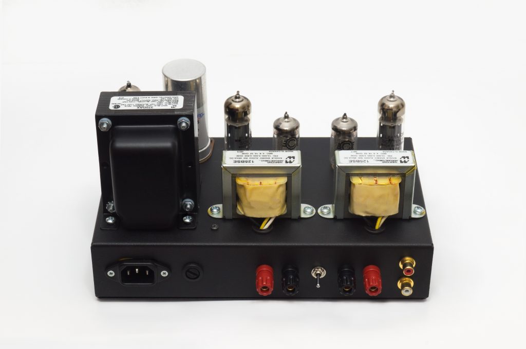
For building this stereo version I needed to design a new power supply because the amplifier doubles the power requirements of the original. I also had to replace the EZ80 rectifier tube with an EZ81 tube.
Here you are the final schematic:
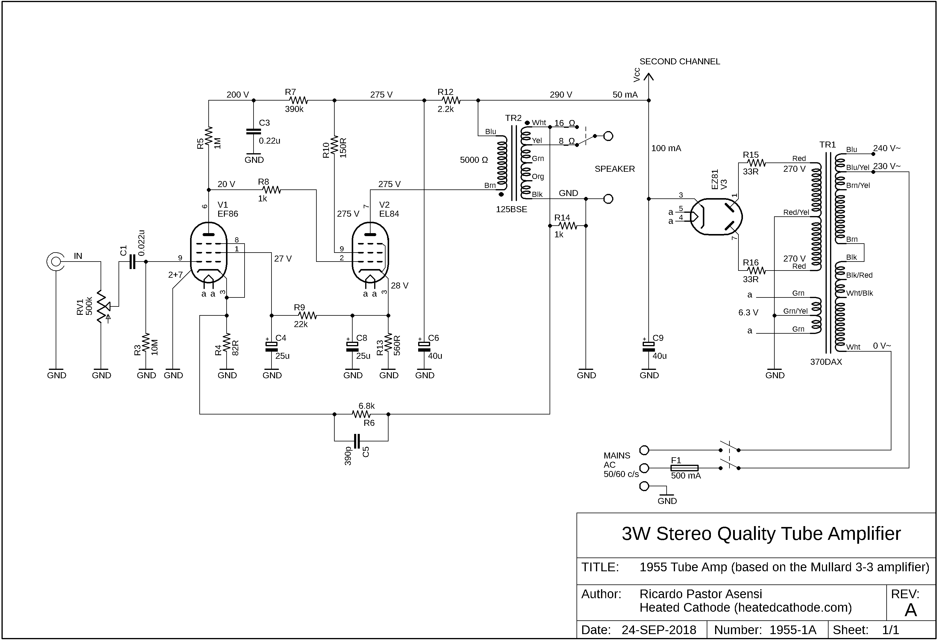
Download the 1955-1 schematic (PDF)
This parts list provides the manufacturer and part number for all of the electronic components that were used to build this device. Additionally, you can find the data sheets for each of these components.
AC mains voltage varies by country, but you can wire the primary windings of the supply transformer according to your voltage for 100, 110, 120, 200, 220, 230, 240 V, as you can see in the universal primary wiring diagram below. This transformer is designed to operate with utility frequencies (power line frequency) of 50 or 60 Hz.
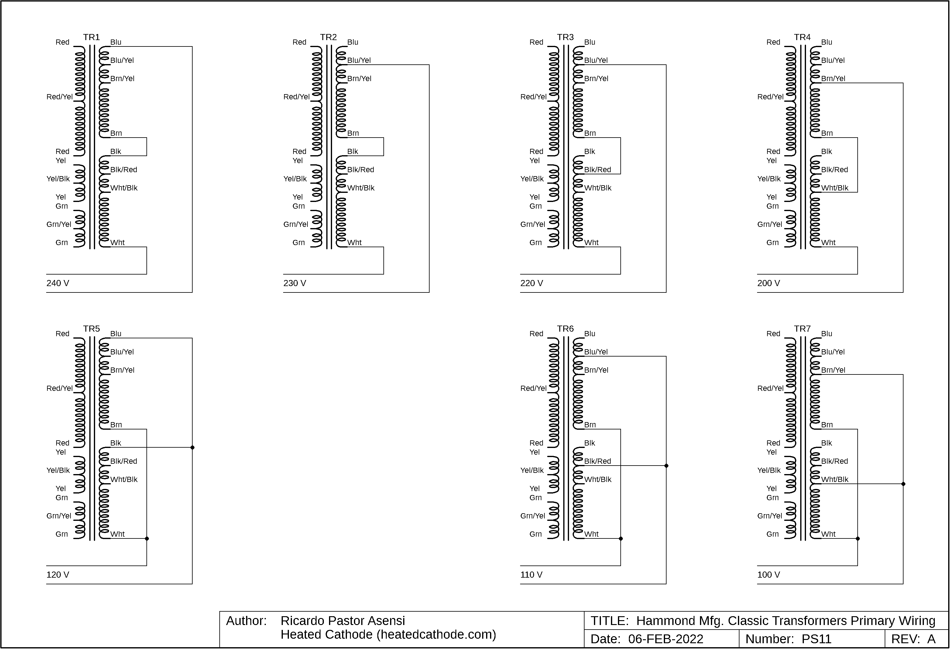
Download the mains transformer wiring diagram (PDF)
I have tested the amplifier under the 230V 50Hz mains power in Spain, with a pair of Wharfedale DIAMOND 10.0 speakers and it sounded great. You can see its performance on measurements page. The sensitivity of the amplifier is 100 mV rms for 3 W rms output per channel.
Other versions of the 1955 model
Above, I described the first version of this audio amplifier, which I built during the summer of 2018 and then used and tested at home for several years.
I later built the following versions of this amplifier.
The Gen2 version of the 1955 model features a mains voltage selector switch for 100, 120, 230 and 240 V AC, 50/60 Hz, a speaker impedance selector switch for 4, 8 and 16 ohms, and a 6.3 V incandescent pilot lamp.
The 1955-3 version incorporates the original Mullard 3-3 tone controls.