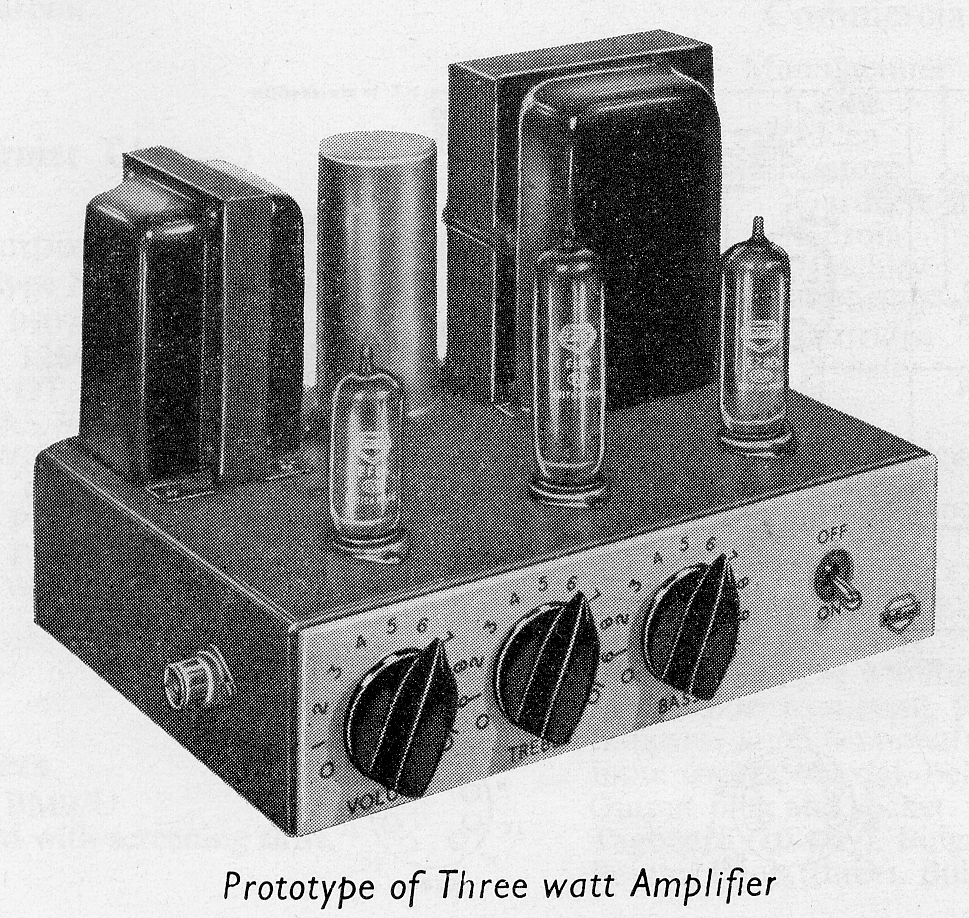
A few years after building the 1955-1 version of the Mullard 3-3 tube audio amplifier, I finally decided to build another version using the original tone-control arrangement. Unlike the earlier tone-control-free version, this 1955-3 version was intended to stay closer to the original Mullard design, both electrically and visually, including the original tone-control layout on the front panel.
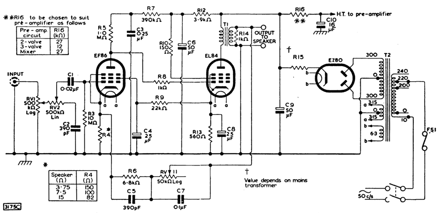
Table of Contents
Original Mullard 3-3 Tone Controls
The tone-control arrangement of the Mullard 3-3 is worth describing because it differs from the type of independent bass and treble boost-and-cut controls commonly found in later audio equipment. In the original circuit, the two controls are better understood as a treble-cut control and a bass-lift control.
RV2, the treble control, acts mainly by varying the attenuation of the upper part of the audio spectrum. It does not provide treble boost; instead, it allows the high-frequency content to be reduced progressively, giving a softer tonal balance when required.
RV11, the bass control, works through the amplifier’s negative feedback network. At low frequencies, reducing the amount of feedback increases the effective gain of the amplifier in that region, producing a bass lift. This is different from simply inserting a conventional bass equalizer into the signal path.
I do not consider this arrangement to be a weakness of the original design. On the contrary, it is part of the character of the Mullard 3-3 circuit and reflects a practical, elegant way of obtaining tone adjustment with relatively few components. Building the 1955-3 version gave me the opportunity to preserve this part of the original design and compare it with the earlier simplified version without tone controls.
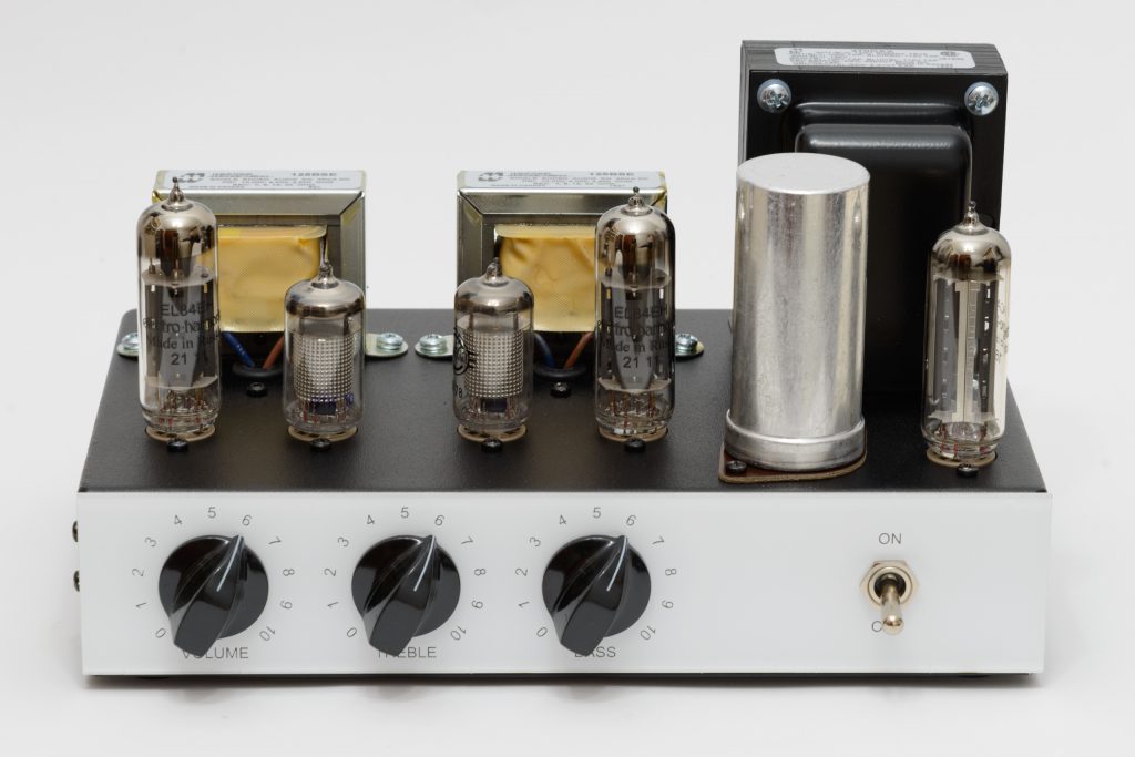
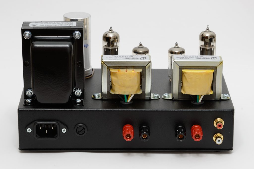
1955-3 Exterior Appearance
The completed 1955-3 amplifier keeps the compact exposed-tube layout of the earlier 1955 versions, while adding the original Mullard-style volume, treble and bass controls on the front panel.
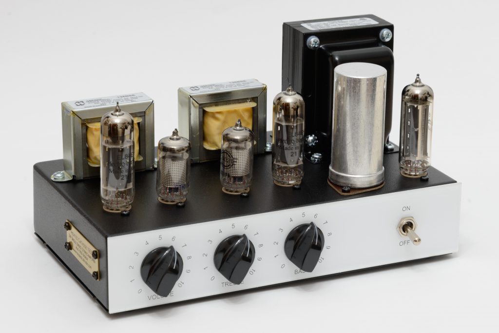
Original Front-Panel Control Layout
The same layout of the tone controls on the front has been maintained as in the original Mullard 3-3 model.
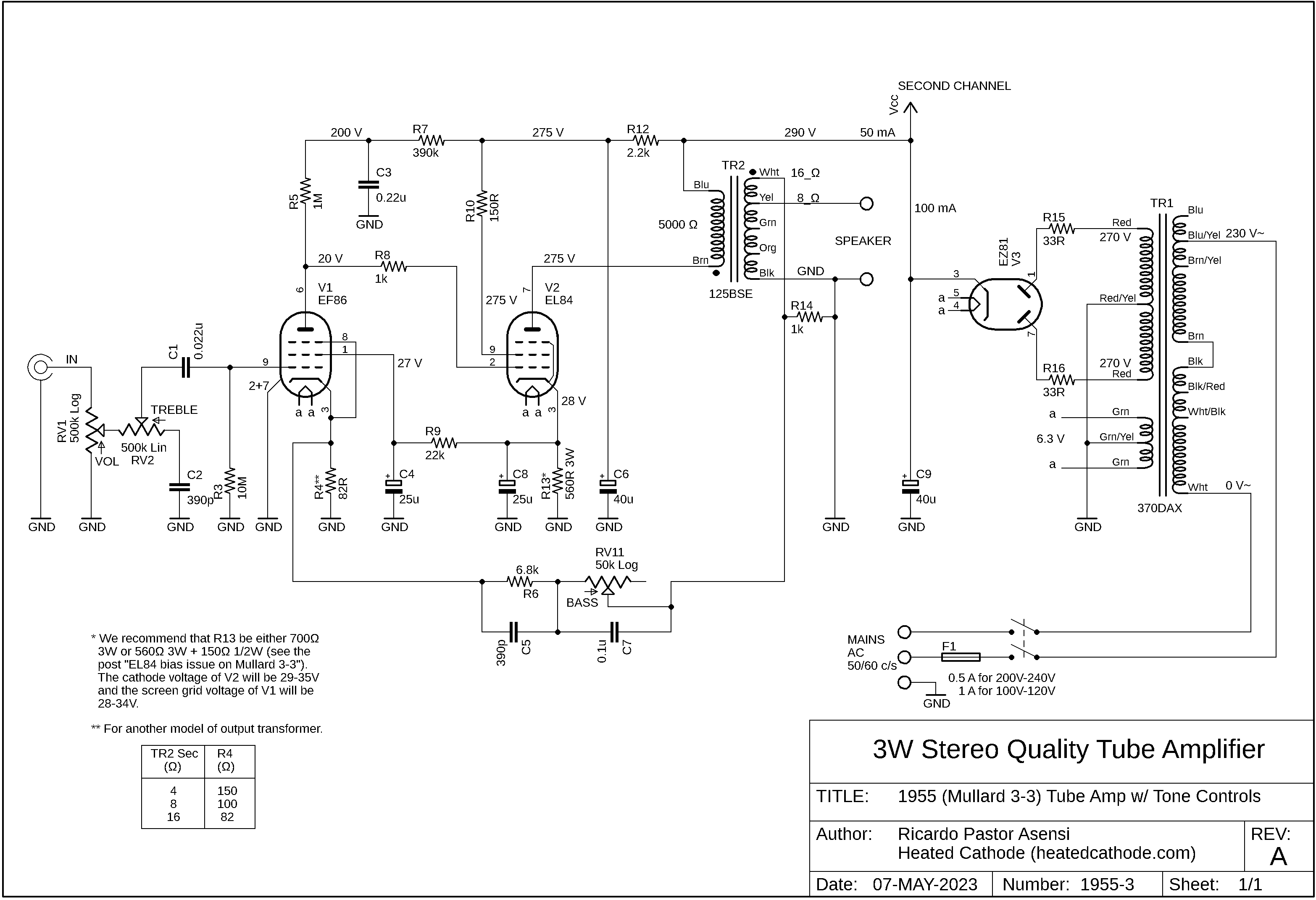
1955-3 Schematic
The schematic below shows the 1955-3 version with the original Mullard 3-3 tone-control network.
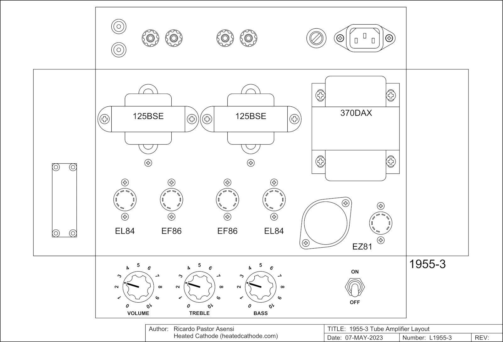
1955-3 Chassis Layout
The chassis layout drawing shows the physical arrangement of the transformers, tube sockets, front-panel controls and rear-panel connectors used in the 1955-3 version amplifier. This version keeps the original Mullard-style tone-control layout on the front panel, with separate volume, treble-cut and bass-lift controls.
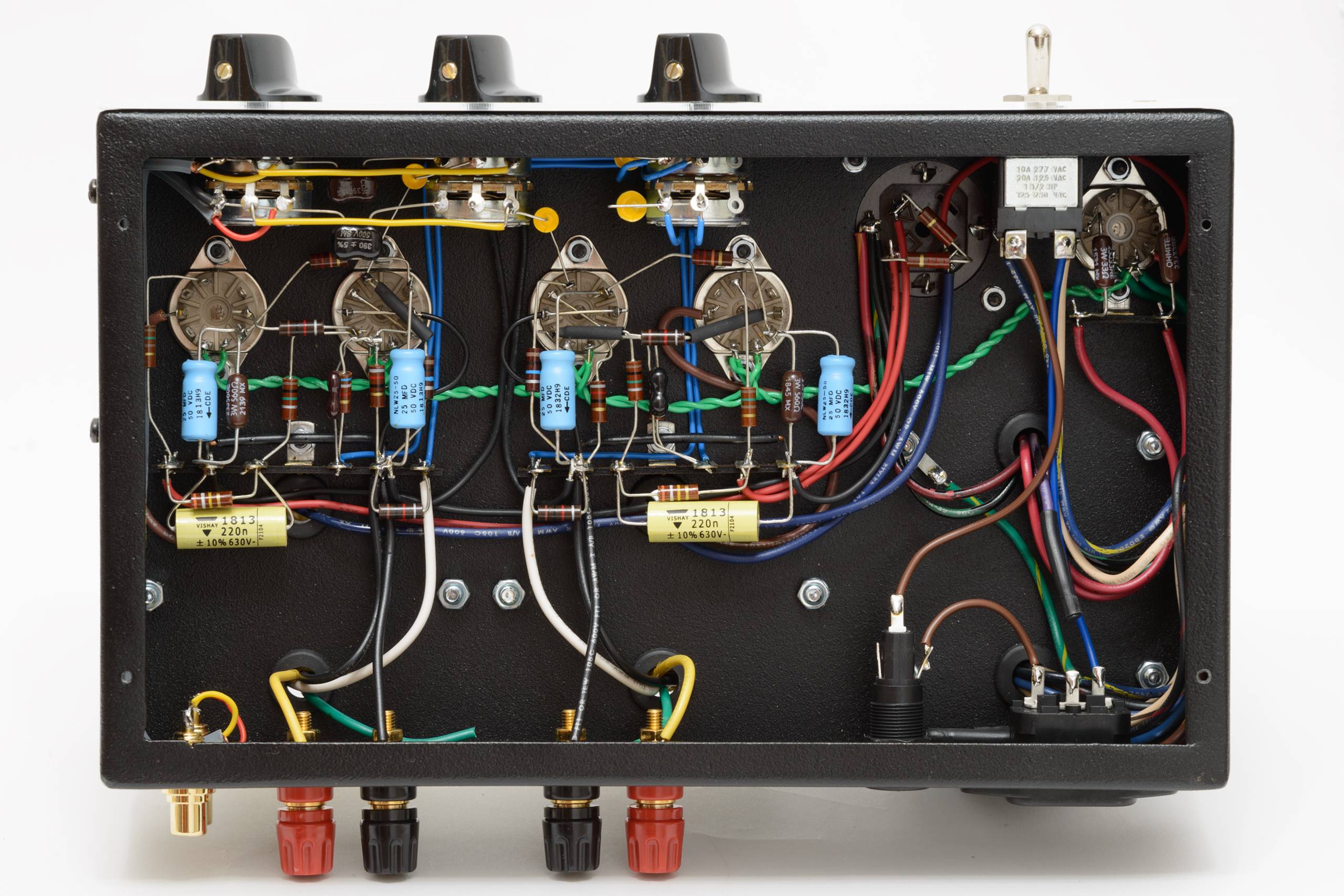
1955-3 Wiring
The underside view shows the point-to-point wiring of the 1955-3 amplifier. Compared with the simplified 1955-1 version, this version requires additional wiring for the original Mullard tone-control network and the three front-panel controls.
The internal layout keeps the wiring as short and direct as possible, while maintaining a clean and serviceable arrangement consistent with the vintage character of the amplifier.