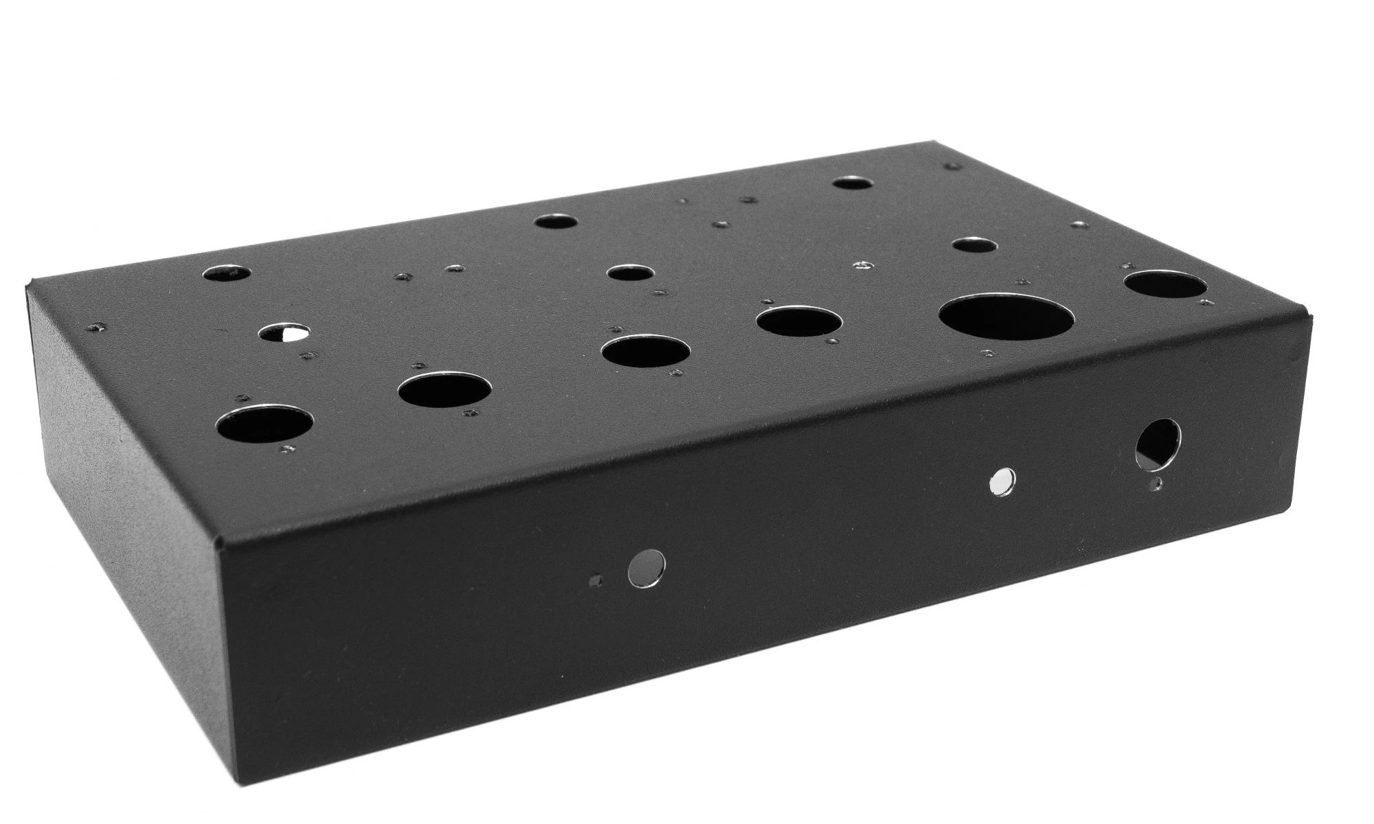
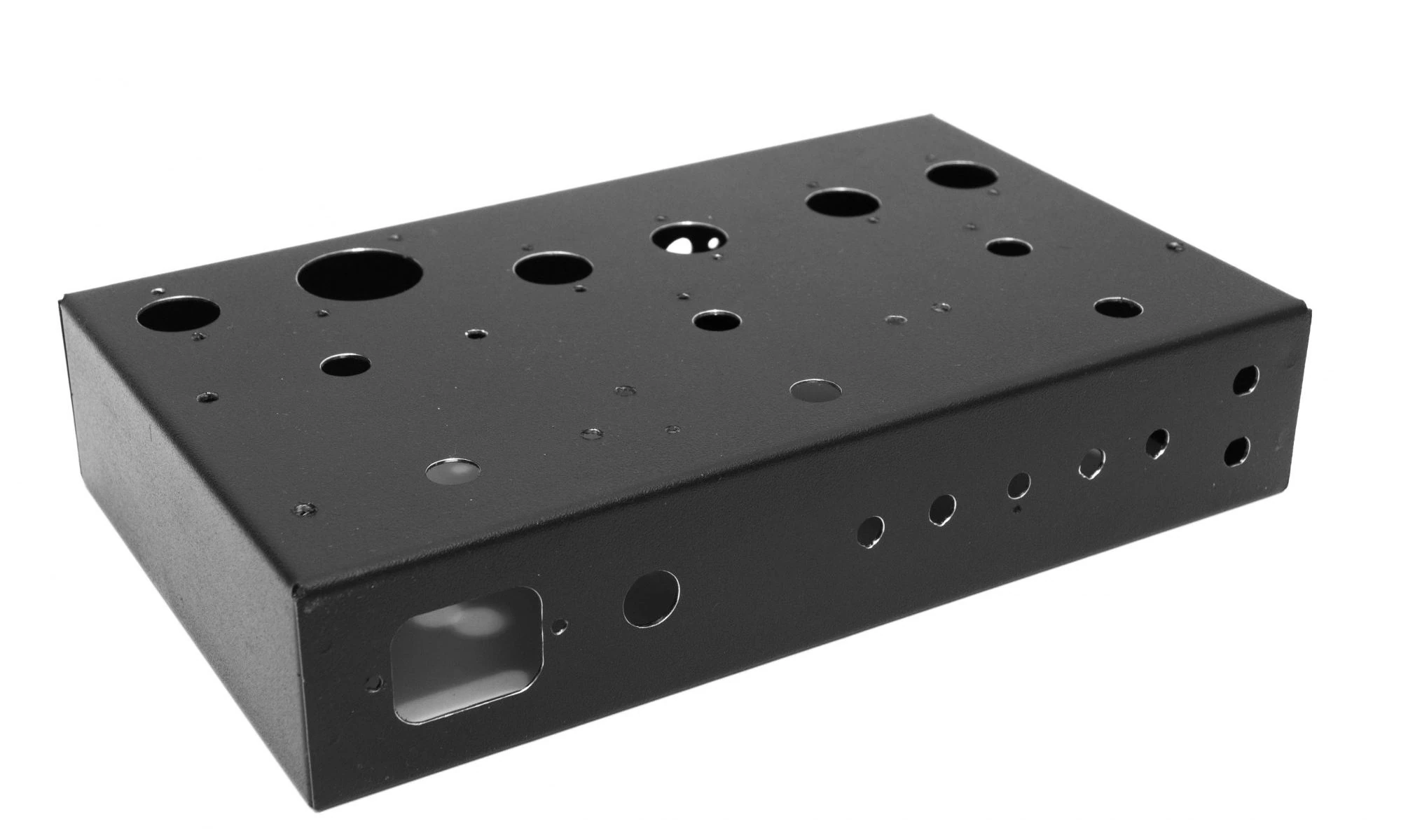
The chassis, used in the prototype and in the first version (1955-1) of the 1955 amplifier, is a heavy-duty steel enclosure made from 21-gauge (0.8 mm) steel sheet and finished in black powder coating.
This construction provides a rigid mechanical structure capable of supporting the weight of the power transformer and output transformers without deformation or vibration.
The chassis includes a removable bottom plate, allowing easy access to the internal wiring during assembly, inspection or maintenance.
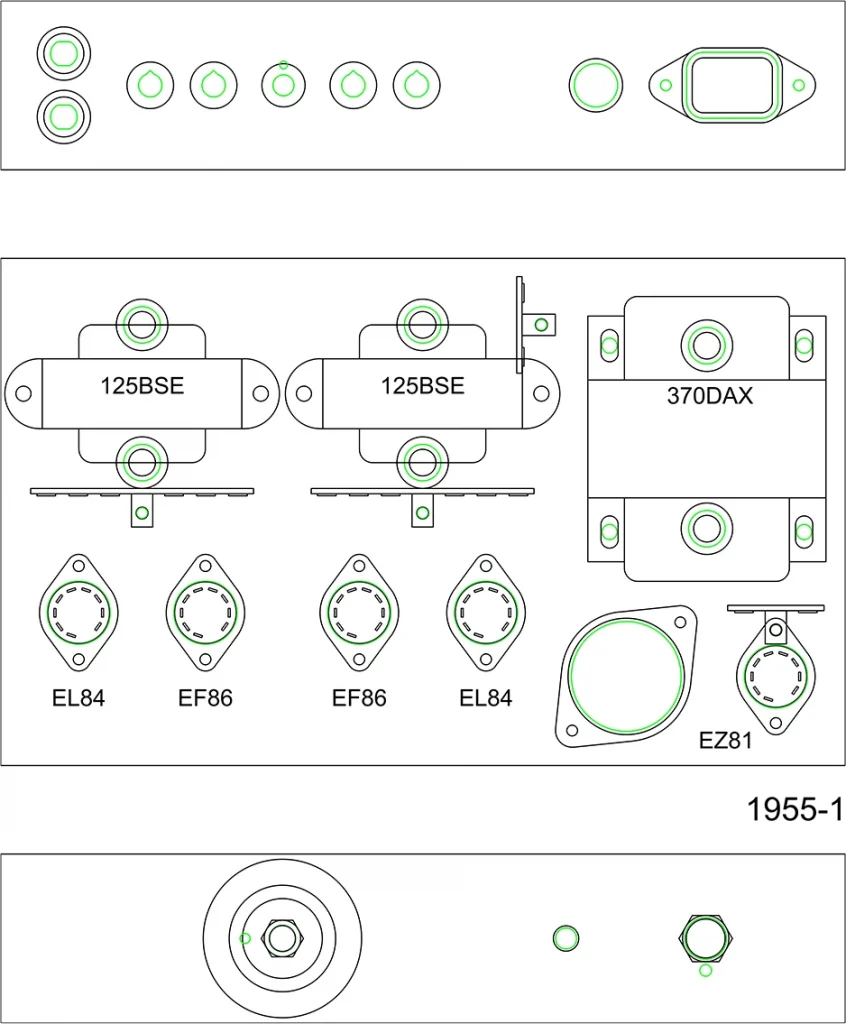
Special attention has been paid to the layout of the components on the top panel:
- The power transformer is located at the rear of the chassis to minimize magnetic coupling with the input stage.
- Output transformers are symmetrically placed to ensure balanced wiring paths for both channels.
- The tube sockets are positioned to provide adequate ventilation and reduce heat accumulation.
- The control elements and connectors are arranged to maintain a clean and functional appearance.
The overall dimensions of the chassis were selected to keep the amplifier compact while still allowing comfortable internal wiring using traditional point-to-point techniques.
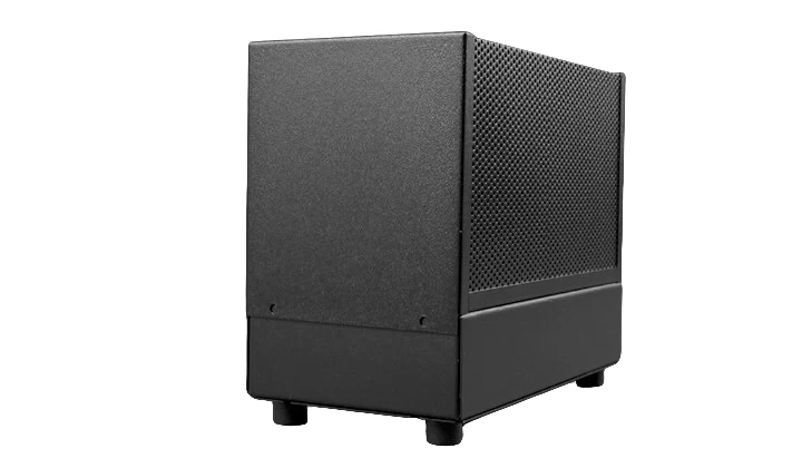
Optionally, this chassis can be fitted with a protective metal cover (Hammond Manufacturing 1451-16BK3) as show below: