The component reference designators have been kept as close as possible to those used in the original schematics.
Resistors
| Reference | Value | Tolerance | Rating | Notes |
|---|---|---|---|---|
| RV1 | 500 kΩ | – | 0.25 W | Logarithmic potentiometer dual 24 mm M8 |
| R3 | 10 MΩ | 5 % | 0.5 W | Carbon composition |
| R4 | 82 Ω | 5 % | 0.5 W | Carbon composition |
| R5 | 1 MΩ | 5 % | 0.5 W | Carbon composition |
| R6 | 6.8 kΩ | 5 % | 0.5 W | Carbon composition |
| R7 | 390 kΩ | 5 % | 0.5 W | Carbon composition |
| R8, R14 | 1 kΩ | 5 % | 0.5 W | Carbon composition |
| R9 | 22 kΩ | 5 % | 0.5 W | Carbon composition |
| R10 | 150 Ω | 5 % | 0.5 W | Carbon composition |
| R12 | 2.2 kΩ | 5 % | 0.5 W | Carbon composition |
| R13 | 560 Ω | 5 % | 3 W | Wirewound |
| R15, R16 | 33 Ω | 5 % | 3 W | Wirewound |
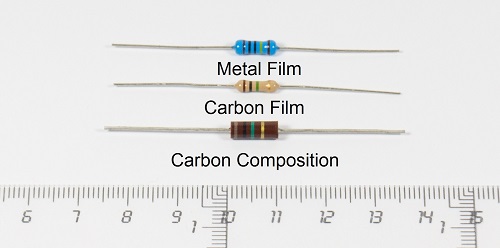
Wherever possible, I have used the same type of resistor as in the original design: carbon-composition resistors. For these parts, I chose a minimum power rating of 0.5 W because they are slightly larger than modern 0.25 W resistors and closer in size to 0.25 W resistors made in the 1960s or earlier. Although they are somewhat oversized for the power they need to dissipate, their higher working-voltage rating makes them a better fit for this circuit.
If a 0.5 W carbon-composition resistor is not available for a specific value, a 1 W carbon-film resistor can be used instead.
The carbon-composition resistors used are from the following manufacturers:
- Ohmite – Little Demon, OF Series (0.5 W ±5 % 350 V) – Datasheet
- Stackpole Electronics, Inc. – RC Series, RC12 (0.5 W ±5 % 350 V)
- TE Connectivity Passive Product – CBT Series, CBT50 (0.5 W ±5 % 350 V) – Datasheet
- Multicomp from element14 – MCRC Series, MCRC1/2 (0.5 W ±5 % 350 V)
The carbon-film resistors used are from the following manufacturers:
- Yageo – Carbon Film Resistors, CFR Series – Datasheet
- Xicon – Carbon Film Fixed Resistors, CF-RC Series 294 or 293 – Datasheet
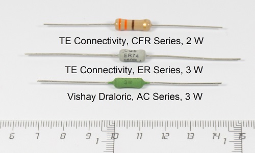
The wirewound resistors used are from the following manufacturers:
- Ohmite – Vitreous Enamel Wirewound Resistors, 20 Series – Datasheet
- Ohmite – Silicone-Ceramic Wirewound Resistors, 40 Series – Datasheet
- Vishay Draloric – Cemented Leaded Wirewound Resistors, AC Series – Datasheet
The 24 mm potentiometer is manufactured by Alpha.
Capacitors
| Reference | Value | Tolerance | Rating | Notes |
|---|---|---|---|---|
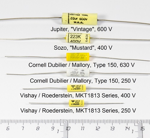
| C1 | 0.022 µF | 5 % | 250 V | Polyester film, CDE Cornell Dubilier / Mallory, Type 150 – Datasheet |
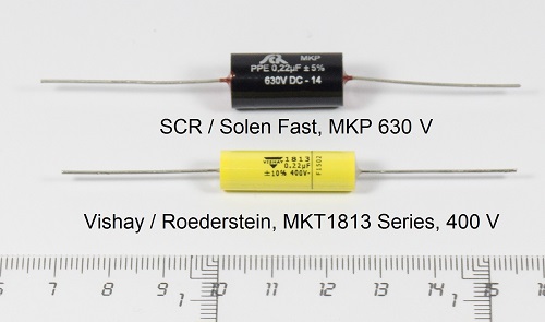
| C3 | 0.22 µF | 10 % | 400 V | Polyester film, Vishay / Roederstein, MKT1813 Series – Datasheet |
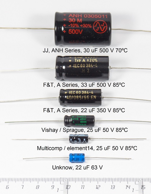
| C4, C8 | 25 µF | 20 % | 50 V | Aluminium electrolytic, Vishay / Sprague – Datasheet |
| C5 | 390 pF | 5 % | 500 V | Standard Dipped Mica, CDE Cornell Dubilier, Type CD15 – Datasheet |
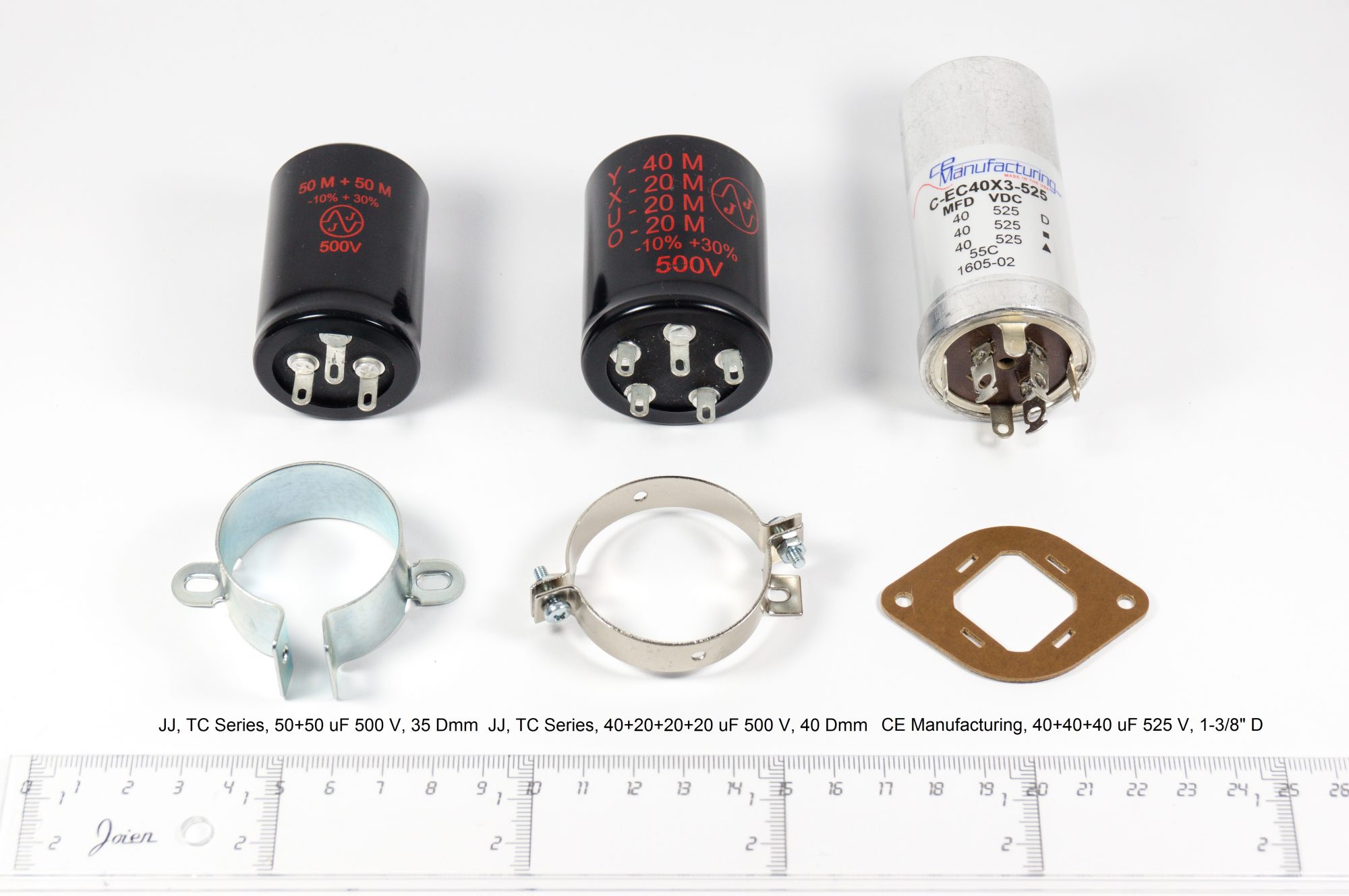
| C6, C9 | 40+40+40 µF | – | 525 V | Aluminium electrolytic, CE Manufacturing |
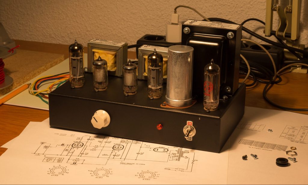
Transformers
| Reference | Type | Model | Datasheet |
|---|---|---|---|
| TR1 | Mains transformer | Hammond Manufacturing 370DAX | Datasheet |
| TR2 | Output transformer | Hammond Manufacturing 125BSE | Datasheet |
Vacuum Tubes / Valves
V1 EF86 – Datasheet
V2 EL84 – Datasheet
V3 EZ81 – Datasheet
Hardware and Miscellaneous Parts
| Part name | Quantity | Notes |
|---|---|---|
| Tube sockets | 5 | Belton Engineering, VT9-ST-1 – Datasheet |
| Mains input socket | 1 | Bulgin, PX0580/28 – Datasheet |
| Fuseholder | 1 | Bulgin, FX0455 – Datasheet |
| Fuse | 1 | 5 mm x 20 mm, 500 mA (1 A for 120 V) |
| Mains switch | 1 | Honeywell, 12TS115-2 – Datasheet |
| Indicator light | 1 | Arcolectric, neon red L104100NAA – Datasheet |
| Input socket RCA | 2 | Neutrik, NYS367 white and red – Datasheet |
| Output socket | 4 | Hirschmann, PKI 10 A Au black and red – Datasheet |
| Impedance switch | 1 | TE Connectivity, FTN0904 – Datasheet |
| Terminal strip 2 way | 2 | Keystone 810 – Datasheet |
| Terminal strip 6 way | 2 | Keystone 825 – Datasheet |
| Solder terminal lug | 4 | Keystone 7327 – Datasheet |
| Grommet 8 mm | 6 | Keystone 742 – Datasheet |
| Insulator for FP Cap | 1 | AES S-H120 |
| ON-OFF plate | 1 | NKK Switches AT214 |
| Chassis steel black | 1 | Hammond Mfg. 1441-16BK3 |
| Chassis bottom cover | 1 | Hammond Mfg. 1431-16BK3 |
| #6-32 Screw 6 pack | 1 | Hammond Mfg. 1421J6 |
| Bumper / Feet | 4 | 3M SJ-5744 BLACK |
| Machine Screw, M3, 10 mm, Steel, Bright Zinc, Flat / Countersunk Head Pozidriv | 2 | M3 10 KRSTMC Z100 |
| Machine Screw, M3, 10 mm, Steel, Chemically Blackened, Pan Head Pozidriv | 14 | M3 10 PRSTMC B100 |
| Washer, Shakeproof, 3.2 mm, 6 mm, Steel, Zinc | 16 | DM3 ITST Z100 |
| Nut, Hex, M3, Steel, Bright Zinc Plated | 16 | M3 HFST Z100 |
| Machine Screw, M4, 10 mm, Steel, Bright Zinc, Pan Head Pozidriv | 8 | M4 10 PRSTMC Z100 |
| Spring Washer, Steel, 4.4 mm Internal, 7 mm External | 12 | DM4 DSSSTWA Z100 |
| Nut, Hex, M4, Steel, Bright Zinc Plated | 8 | M4 HFST Z100 |
| Insulated hook-up wire, solid, 0.8 mm² (18 AWG) black, 300 Vrms min. | ||
| Insulated hook-up wire, solid, 0.5 mm² (20 AWG) black, blue and red, 300 Vrms min. | ||
| Audio signal wire 2 x 0.14 mm² single shielding, black | ||
| Pointer knob | 1 | (see text) |
Knob Options
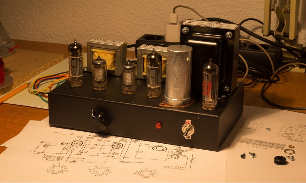
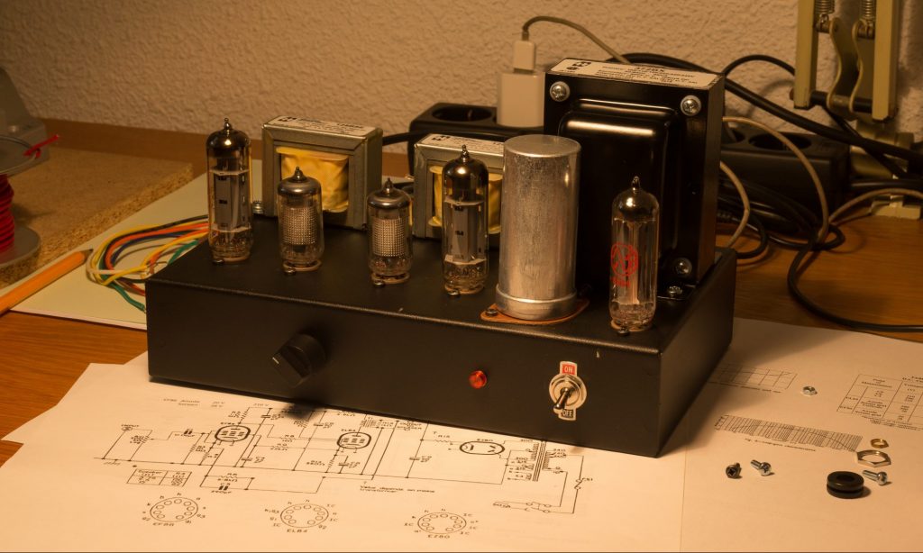
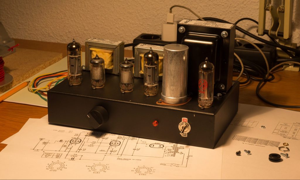
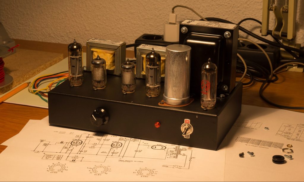
When I checked in 2019, the original pointer knob, Bulgin KX0370, was still available from major electronic component distributors, but I preferred to use a different model selected from the options shown below.
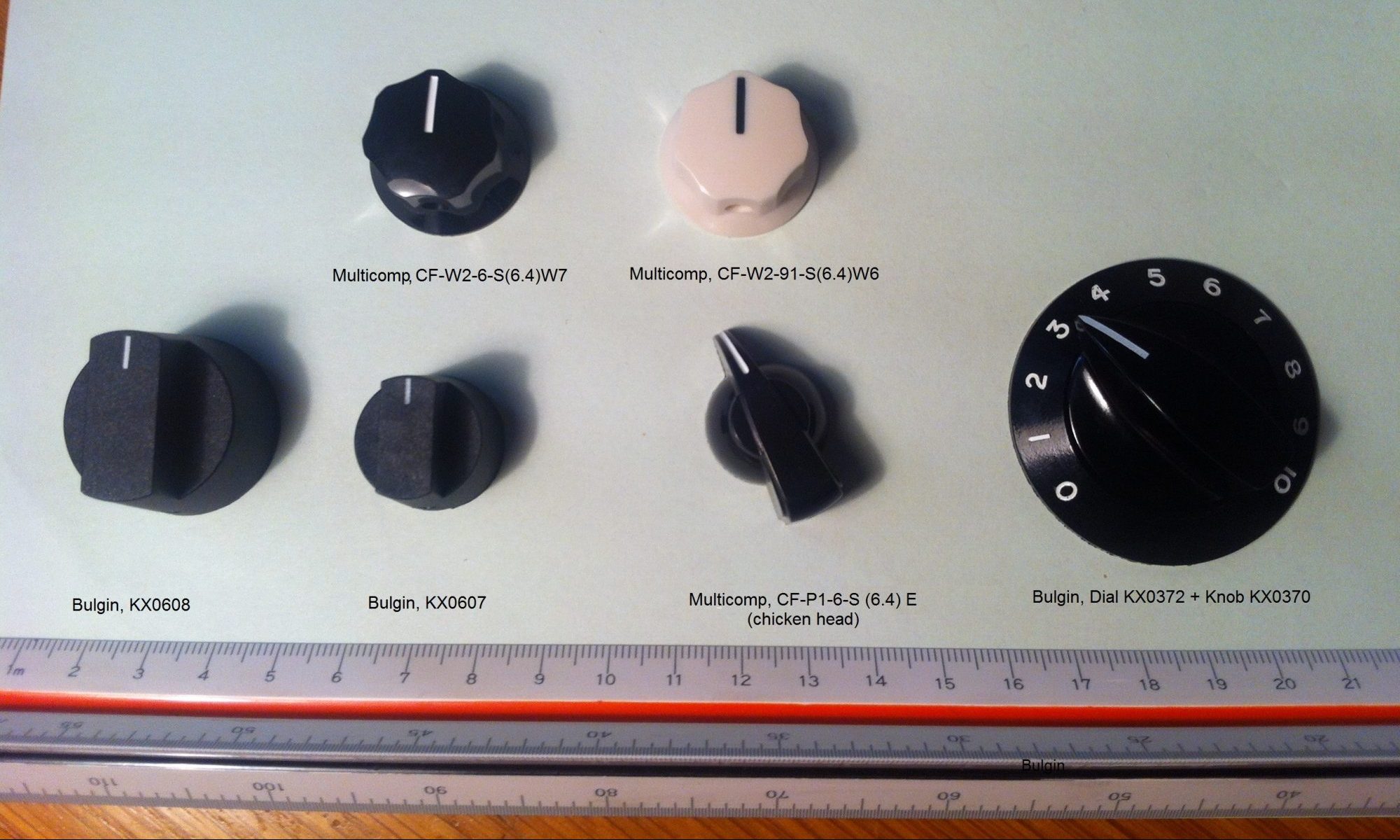
Several knob options were tested on the prototype to compare their visual fit with the amplifier chassis.