The first image shown on this page is the original chassis layout and wiring sketch for the first version of the Model 1955 amplifier, now also referred to as the 1955-1. This amplifier was originally conceived as a point-to-point wired build, following a construction style commonly found in vintage radio receivers and early valve audio equipment.
A good friend of mine, Emilio Roldán, assisted me in defining the arrangement of the components inside the Hammond chassis and drew the sketch showing the position of the main components and their interconnections. The chassis had already been selected according to the size of the transformers, so the drawing became the practical starting point for organizing the tube sockets, passive components, terminal strips and internal wiring.
Emilio’s signature, dated August 26, 2016, appears on the sketch. This original drawing later served as the guide for building the first Model 1955 prototype, whose construction was completed in July 2017.
Original chassis layout and wiring sketch
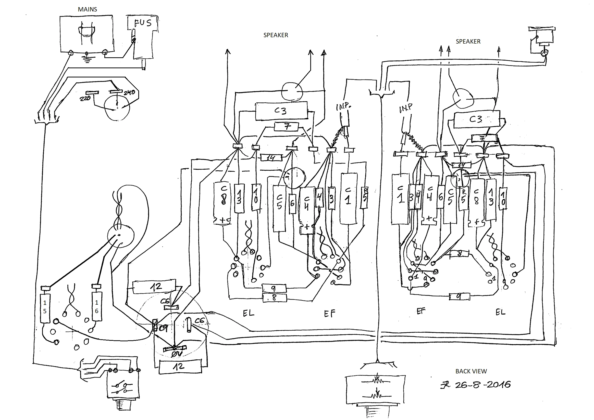
The drawing shows the intended position of the main components inside the chassis, together with the most important wiring connections. It combines both a physical layout and a practical wiring guide, rather than being only an electrical schematic.
This kind of drawing was especially useful during the construction of the first prototype, because it helped define the relationship between the tube sockets, transformers, speaker terminals, input wiring, grounding points and passive components before the amplifier was assembled.
Underside view of the completed amplifier
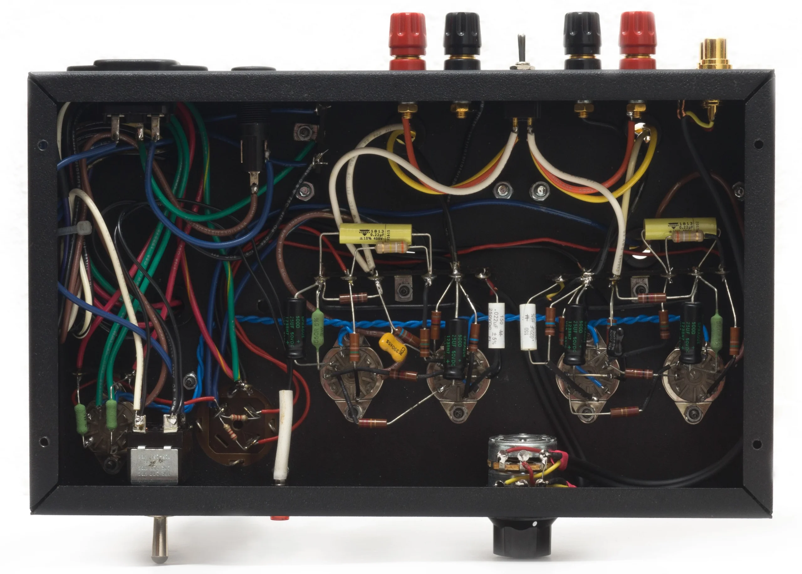
The underside view shows the final point-to-point wiring of the 1955-1 amplifier. The construction follows the original layout sketch closely, with the components mounted directly between tube sockets, terminal strips and connection points.
The internal wiring was arranged with short signal paths and clear separation between different parts of the circuit. Low-level audio wiring, heater wiring, power supply wiring and speaker output wiring were routed as cleanly as possible inside the limited space of the chassis.
Wiring approach
The 1955-1 was not built on a printed circuit board. Instead, it uses point-to-point wiring, which is a traditional construction method often used in valve amplifiers and vintage electronic equipment.
This approach makes the internal construction more visible and easier to understand, but it also requires careful planning. The physical position of each component affects the length of the wires, the grounding scheme, the risk of hum pickup and the accessibility of the circuit for later inspection or maintenance.
The original layout sketch was therefore an important part of the design process. It allowed the amplifier to be treated not only as an electrical circuit, but also as a physical object with transformers, sockets, controls, terminals and wiring paths that had to coexist inside the same chassis.
Signal wiring
The low-level audio input wiring uses shielded cable. This helps protect the input signal from noise and hum, especially near the first amplification stage, where the signal level is still very small.
The input wiring should be kept away from mains wiring, heater wiring and power supply connections wherever possible. In a small valve amplifier chassis, complete separation is not always possible, but careful routing helps reduce unwanted noise.
The aim was to keep the signal path short and direct, while avoiding unnecessary crossings with higher-current or higher-voltage wiring.
Heater wiring
The heater wiring is one of the most important areas to consider in a valve amplifier layout. Heater wires carry AC current and can induce hum into nearby signal wiring if they are badly routed.
In this amplifier, the heater wiring is identified with blue wire. It is routed as neatly as possible and kept away from sensitive input connections. Where practical, heater wiring should be run close to the chassis and separated from low-level audio wiring.
Power supply and high-voltage wiring
The power supply and high-voltage wiring were kept distinct from the signal wiring. This is especially important in a compact chassis, where the power transformer, rectifier, filter capacitors, output transformers and audio stages are all relatively close to each other.
The B+ wiring uses red wire, making the high-voltage supply lines easy to identify during construction and later inspection.
Grounding
The grounding layout is an essential part of the wiring of any valve amplifier. Poor grounding can create hum, noise or ground loops, even when the schematic itself is correct.
The 1955-1 wiring follows a practical layout-oriented grounding approach, keeping ground connections short and avoiding unnecessary wiring runs. The input ground, signal ground and power supply ground must be arranged carefully so that high-current return paths do not interfere with the low-level input signal.
The protective earth connection is a safety-critical part of the amplifier and must be firmly bonded to the metal chassis.
Wire types used
The following wire types were used for the internal wiring of the 1955-1 amplifier:
| Use | Wire type | Section / gauge | Colour or note |
|---|---|---|---|
| Circuit ground hook-up wiring | Solid insulated wire | 0.8 mm² / 18 AWG | Black |
| Low-current ground hook-up wiring | Solid insulated wire | 0.5 mm² / 20 AWG | Black |
| Heater wiring | Solid insulated wire | 0.5 mm² / 20 AWG | Blue / Green |
| B+ / power wiring | Solid insulated wire | 0.5 mm² / 20 AWG | Red |
| Output Transformer secondary wiring | Stranded transformer wire | 0.32 mm² / 22 AWG | Reused Hammond transformer wire |
| Audio input wiring | Shielded signal cable | 2 × 0.14 mm² | Single shield, black or grey |
Using different colours for heater and power supply wiring makes the circuit easier to follow visually and reduces the chance of mistakes during assembly, checking or later servicing.
Construction notes
When wiring a valve amplifier point-to-point, the physical layout is almost as important as the schematic. A correct schematic can still result in a noisy amplifier if the wiring is poorly routed.
For this build, the main wiring objectives were:
- to keep the audio signal path short.
- to route heater wiring away from sensitive input connections.
- to keep power supply wiring separate from low-level audio wiring.
- to make the B+ wiring easy to identify.
- to maintain a clean and serviceable underside layout.
- to keep the final amplifier visually close to the original layout sketch.
Safety note
This amplifier contains potentially lethal voltages. High voltage may remain present inside the chassis even after the amplifier has been switched off, especially in the power supply capacitors.
Before working inside the amplifier, the filter capacitors must be safely discharged and the circuit must be checked with a suitable meter. Mains wiring, fuse wiring, protective earth connections and high-voltage wiring should only be assembled or modified by someone qualified to work safely with this type of equipment.
Inspection checklist
Before powering the amplifier for the first time, the following points should be checked carefully:
- protective earth continuity between the IEC inlet, chassis and exposed metal parts.
- correct mains fuse value and fuse wiring.
- absence of loose wire strands or solder bridges.
- correct heater wiring continuity.
- correct B+ wiring against the schematic.
- correct speaker output wiring.
- correct input wiring and shield connection.
- no short circuits between B+, heater wiring and chassis ground.
- no components touching the chassis unintentionally.
- correct polarity of electrolytic capacitors.
This final inspection is especially important in a point-to-point wired amplifier, where every connection is made manually and the physical layout directly affects both safety and performance.