1.- Voltage and current requirements
High tension:
Idc per channel = UV2k / R13 = 28 V / 560 Ω = 0.05 A = 50 mA
Udc = 310 V
Idc = 2 x 50 = 100 mA
Low tension:
| Tube | Uf | If | Qty, |
|---|---|---|---|
| EF86 | 6.3 V | 0.2 A | 2 |
| EL84 | 6.3 V | 0.76 A | 2 |
thus
Uf = 6.3 V
If = 2 x (0.2 + 0.76) = 1.92 A
2.- Power supply elements
It is convenient to use a full-wave rectifier with capacitor input filter.
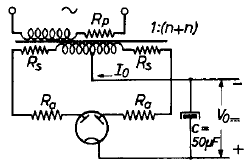
We require 100 mA at 310 V. One of the full-wave rectifier tubes having the proper rating is the EZ81 [Datasheet] with a maximum dc output current of 150 mA, a maximum plate voltage per plate of 350 V rms, a peak inverse voltage of 1300 V, and a cathode to heater voltage of 500 V. This tube has the same shape and socket of the other amplifier tubes.
The maximum capacity of the input capacitor of smoothing filter for this tube is 50 µF. The capacitor working voltage must be at least the peak transformer output voltage.
The EZ81 heating specifications are Uf = 6.3 V and If = 1.0 A.
If we connect the heater of the EZ81 to the low-tension circuit of the other tubes (and not in a separate transformer low-tension heating winding), the low voltage requirements are
Uf = 6.3 V
If = 1.92 + 1.0 = 2.92 A.
And the total drawing power of the circuit is
Pt = 310 x 0.1 + 6.3 x 2.92 = 49.40 VA
We need a transformer with a minimum of 50 VA and with a high-tension secondary voltage to be determined with the help of the following EZ81 load graph.
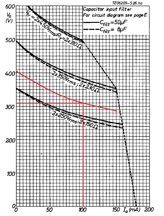
We need to supply 100 mA at 310 V. Hence, we mark the point 100, 310 in our graph, and we draw a parallel curve of the 2 x 350 V and 2 x 250 V curves that includes that point.
This curve that we have drawn intersects the abscissa axis (Io = 0) in Vo = 405 V. Which determines a no-load transformer peak voltage of 405 V, and a load transformer RMS voltage of
Us = 405 / √2 = 286 V rms
With the data obtained we select the power transformer from the follow list provided by Hammond Manufacturing
| Part No. | VA | Output voltage RMS no load | Output voltage RMS | Output Fil-1 | Output Fil-2 | Size |
|---|---|---|---|---|---|---|
| 370BX | 55 VA | 2x 300.7 V | 2x 275V @ 58mA | 6.3V @ 2A | 5V @ 2A | X7 |
| 370CX | 59 VA | 2x 304.4 V | 2x 275V @ 75mA | 6.3V @ 2.5A | 6.3V @ 0.6A | X7 |
| 370DX | 86 VA | 2x 302.7 V | 2x 275V @ 104mA | 6.3V @ 3A | 5V @ 2A | X8 |
| 370DAX | 76 VA | 2x 286.8 V | 2x 260V @ 104mA | 6.3V @ 3.5A | X8 | |
| 372BX | 98 VA | 2x 323.1 V | 2x 300V @ 115mA | 6.3V @ 3A | 5V @ 2A | X10 |
Our choice is the 370DAX, which has the proper specifications
| Parameter | We require | 370DAX |
|---|---|---|
| Power (VA) | 50 | 76 |
| Filament 6.3 V current (A) | 2.92 | 3.5 |
| H.T. Voltage no-load (V) | 2 x 286 | 2 x 287 |
| H.T. Current (mA) | 100 dc | 104 ac |
3.- Overvoltage conditions
If the load should be removed accidentally, the DC voltage output will rise to the no-load peak transformer output voltage
Um = √2 · 287 = 406 V
The working voltage of the capacitor input filter must be greater than 406 V.
We can safely connect the EZ81 heater to the filament circuit of the other tubes, whose transformer filament circuit center tap is connected to 0 V, since the insulation voltage cathode to heater of the EZ81 is 500 V that is greater than 406 V.
In these conditions the peak inverse voltage over the rectifier tube is
Uim = 2 · Um = 2 · 406 = 812 V
Since the rated peak inverse voltage of the EZ81 tube is 1300 V, it is safe to use.
4.- Transformer winding resistance
The power transformer equivalent internal winding resistance Ri is given by
Ri = Rs + n2 · Rp
where
Rs : the resistance of half of the secondary winding.
Rp : the resistance of the whole primary winding.
n : the ratio of the number of turns on half of the secondary winding to the number of turns on the primary winding.
From the transformer 370DAX datasheet, the winding resistances are
12.12 Ω at primary winding number one (120 V)
13.10 Ω at primary winding number two (120 V)
222.9 Ω at whole secondary winding (573.5 V)
therefore
Rs = 222.9 / 2 = 111 Ω
Rp (for 120 V) = 12.12 || 13.10 = 6 Ω
Rp (for 240 V) = 12.12 + 13.10 = 25 Ω
n (for 120 V) = Us / Up = 287 / 120 = 2.4
n (for 240 V) = Us / Up = 287 / 240 = 1.2
and
Ri (for 120 V) = 111 + 2.42 · 6 = 145 Ω
Ri (for 240 V) = 111 + 1.22 · 25 = 147 Ω
5.- Anode limiting resistor
Next, we determine the minimum value for the anode protection resistor Rt at the power transformer output from the EZ81 data sheet following graph
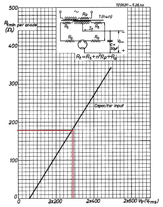
For a secondary transformer voltage of 2 x 286 V rms the value of Rt must be at least 180 Ω.
Thus
Ra = Rt – Ri = 180 – 145 = 35 Ω
We choose a standard value of 33 Ω
If we assume the average current per resistor to be 100 / 2 = 50 mA, the average dissipated power per resistor is given by
P = I2 · R = 0.052 · 33 = 0.083 W
But we have finally decided to use 33 Ω 3 W wire wound resistors to give it a retro aspect.