From time to time I receive thoughtful questions about the mechanical layout of the 1955 amplifier—especially around transformer placement and hum performance. One question comes up often enough that it’s worth answering properly here.
Question
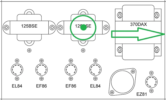
“The alignment of the power transformer relative to the output transformers: they are usually mounted at 90° to each other, but in your build they are not. Since the PT is very close to the right OT, do you experience any induced hum there? I do agree that the layout looks better this way, though.”
Power transformer and output transformer orientation
The “mount transformers at 90°” guideline is a good rule of thumb, but it’s easy to misread it when looking at a top-down layout. What really matters is the direction of each transformer’s magnetic field (its magnetic axis) in three dimensions—not just how the laminations look from above.
In the 1955 layout, the power transformer’s magnetic field axis is horizontal, oriented left-to-right across the chassis. The output transformers’ magnetic field axes, on the other hand, are oriented vertically—perpendicular to the plane of the chassis (and therefore perpendicular to the drawing when viewed from above).
This means that, even though the transformers don’t appear “at 90°” in a purely top-down sense, their magnetic axes are effectively orthogonal in 3D space. That’s the reason the layout behaves as intended.
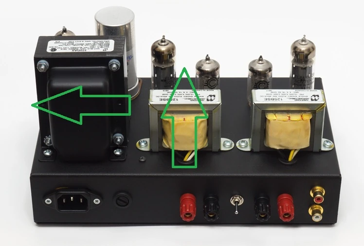
Do I get induced hum with the close spacing?
In practice, I have not experienced induced hum from the power transformer into the right-side output transformer, despite the relatively close proximity. With the amplifier operating normally, hum levels remain consistent with what I’d expect from a careful tube build, and there is no additional transformer-coupling artefact that appears specifically because of that placement.
As always, transformer coupling is a real phenomenon and it can vary depending on transformer construction, exact mounting height, chassis material, and wiring dress. For that reason, I still treat hum performance as something to verify during prototyping and final testing rather than relying on rules alone.
A practical takeaway
If you’re building an amplifier and you’re evaluating transformer orientation, don’t judge only by the top-down picture. Consider the transformer’s magnetic axis (in 3D), keep sensible spacing where possible, and confirm with a simple hum check during bring-up. The classic 90° guideline is useful—but it’s the underlying physics that decides whether a given layout will be quiet.
If you have questions about the 1955 layout or want to see more design notes like this, feel free to email me. I’m always happy to discuss the details.