Mullard 3-3 Printed Circuit Board
Mullard 3-3 printed circuit board designed to simplify assembly of the Model 1955 vacuum-tube audio amplifier, with schematics, wiring diagrams, and notes for implementing the original tone controls.
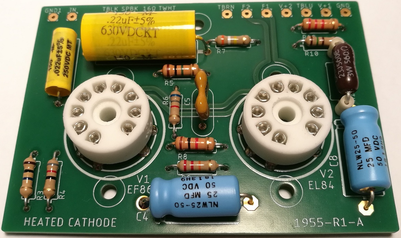
Mullard 3-3 printed circuit board designed to simplify assembly of the Model 1955 vacuum-tube audio amplifier, with schematics, wiring diagrams, and notes for implementing the original tone controls.
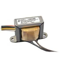
An output transformer has its own frequency response, but the amplifier’s final response depends on the complete circuit. Negative feedback extends the bandwidth and improves low-frequency performance beyond what the transformer data alone suggests.
A reader asked why the power transformer isn’t mounted at 90° to the output transformers in my 1955 build, and whether that close spacing causes induced hum. Here’s why the layout works in practice.
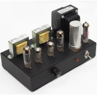
This document aims to serve as a guide for building the 1955 Gen2 vacuum tube amplifier. It can also be used for assembling the simplified wiring version, the 1955 Gen1.
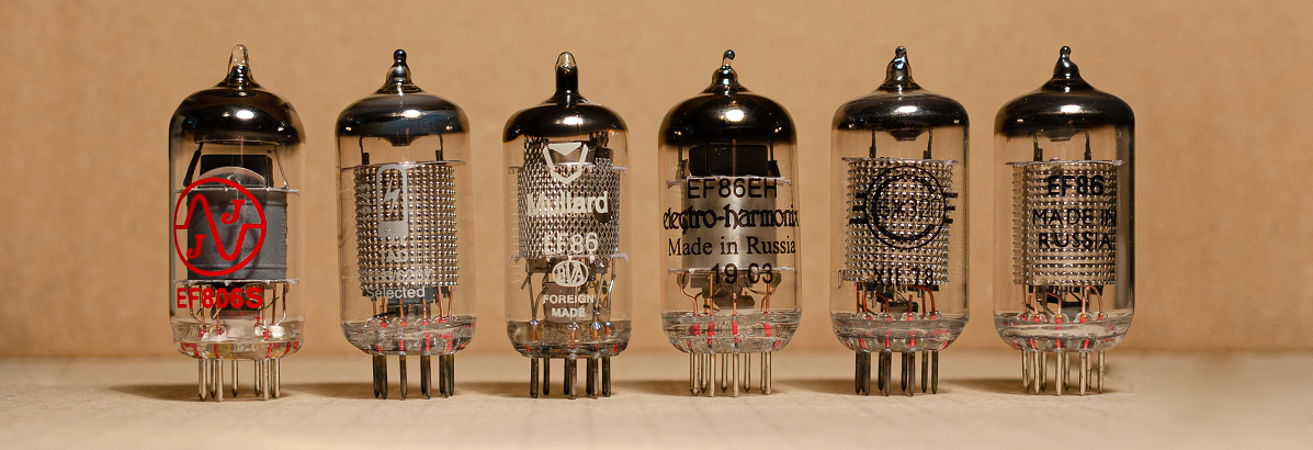
In the original Mullard 3-3 design the operating point of the EL84 tube is highly dependent of the amplification factor of the EF86 tube.
How to calculate a voltage divider to reduce the input to the tube amplifier
It’s now been more than a year and a half since I first put the 1955-1 prototype tube audio amplifier into regular use in my living room, and I’m pleased to report that it has operated reliably every day without a single breakdown. Over this period the amp has typically been in service for two

A new set of measurements for the Model 1955 Mullard 3-3 tube amplifier, including frequency response, phase shift, distortion, operating voltages, power consumption and sensitivity.