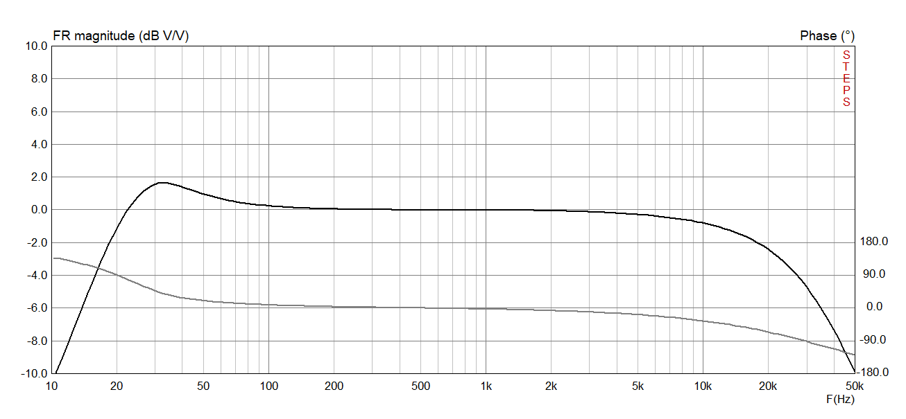
The response remains within approximately 2 dB from 20 Hz to 20 kHz.
The Model 1955 is my stereo interpretation of the classic Mullard 3-3, a small single-ended Class-A tube amplifier introduced in 1955. The circuit uses an EF86 voltage amplifier stage directly coupled to an EL84 output stage, with tube rectification and point-to-point wiring in keeping with the spirit of the original design.
I have now added a complete set of performance measurements for the amplifier. The tests were carried out after the circuit had been operating for one hour at an ambient temperature of approximately 25 °C, so the operating points were measured under stable, warmed-up conditions.
What was measured
The measurements page now includes the main DC operating conditions, current calculations, power consumption, start-up voltages, frequency response, phase shift, distortion, linearity and sensitivity. This makes it easier to compare the finished amplifier with the original Mullard 3-3 operating points and to see how the practical transformer choices affect the final circuit.
In this prototype, the voltage at the C9 filter capacitor is 290 V DC instead of the 310 V DC shown in the original reference circuit. The output transformer also has a different primary winding resistance from the original design, so the value of R8 was changed from 3.9 kΩ to 2.2 kΩ to equalize the plate and screen-grid voltages of the EL84 output tube.
Frequency response and phase shift
At 0.3 W RMS output power, the amplifier response is essentially flat within approximately 2 dB from 20 Hz to 20 kHz. The measurements include graphs for the standard circuit and for the enhanced circuit, where the feedback capacitor C5 was removed and the C8 cathode bypass capacitor was increased to 100 µF.
These graphs are useful because they show not only the amplitude response, but also the phase shift across the audio band. For a simple single-ended tube amplifier with an output transformer, this gives a clearer picture of the real behaviour of the circuit than a single power-output figure.
Sensitivity and output power
The measured input sensitivity is 100 mV RMS at 1 kHz for an output of 3.48 W RMS. With this input level, the voltage at the EL84 anode reaches 132 V RMS, which corresponds to approximately 3.48 W RMS into the 5 kΩ reflected load.
The total voltage gain is approximately 1320 times, or 62 dB. Most of this gain is shared between the EF86 input stage and the EL84 output stage, which is one of the reasons the Mullard 3-3 design can achieve full output with a relatively low input signal.
Full measurement results
The complete graphs and operating-point tables are available on the Model 1955 measurements page. They include the standard and enhanced frequency-response curves, distortion measurements, linearity graph, sensitivity test and oscilloscope captures taken during the prototype characterization.