How EF86 tube variability, direct coupling and the limited authority of screen-grid DC feedback can move the output stage far from its intended operating point
Summary. In a faithful Mullard 3-3 implementation, the EL84 operating point is strongly influenced by the individual EF86 installed in the voltage-amplifier stage. In my amplifiers, some EF86 tubes produced the expected cathode voltage of about 28 V, while others raised it to approximately 40 V. With the original 560 ohm cathode resistor, those readings correspond to about 50 mA and 71 mA of total cathode current respectively. The higher value is roughly 43% above the intended current. It reduces the magnetic headroom of the single-ended output transformer, moves the EL84 away from its intended operating region, and can increase distortion and component stress. The circuit must therefore be checked with the actual tubes installed, and the cathode-bias resistance should be adjusted when necessary.
Safety note. Tube amplifiers contain potentially lethal voltages, including stored charge after the equipment has been switched off. The measurements and modifications described here must be carried out only by suitably qualified personnel using appropriate procedures, insulated tools and correctly rated test equipment.
Originally written in August 2021, this article was last updated in July 2026.
Why the EF86 matters in this circuit
The EF86 is a low-noise pentode developed for audio-frequency voltage amplification, especially in high-gain input stages. In the Mullard 3-3 it is used under unusual conditions: a 1 megohm anode load, low anode and screen-grid voltages, and DC coupling from the EF86 anode to the EL84 control grid through the 1 kilohm grid-stopper resistor, with no interstage coupling capacitor.
That direct connection is central to the design. It avoids an interstage coupling capacitor and helps Mullard obtain the required gain and feedback margin from only two amplifying tubes. It also means that a change in the EF86 operating point is passed directly to the EL84 grid. The EL84 bias is therefore influenced not only by the output tube and its cathode resistor, but also by the characteristics of the particular EF86 fitted in V1.
Tube-to-tube variation is normal. Transconductance, anode current, internal resistance and the resulting anode voltage can all differ from published average values. In a conventional RC-coupled amplifier, part of this spread is isolated by the coupling capacitor and the independent grid-bias network of the output stage. In the directly coupled 3-3, it is much more visible.
How the issue first appeared
When I built the first prototype of the Model 1955 amplifier in July 2017, I had already decided to keep the signal circuit as faithful as possible to the original Mullard 3-3. The intention was to reproduce the topology first and verify its behaviour by measurement rather than by assumption.
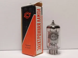
For the EF86 stage I initially bought Russian NOS (New Old Stock) EF86-equivalent tubes with the -C- factory logo. Their prominent metal screening gave them a suitably period appearance, and they were less expensive than many other EF86 types.
After completing the assembly, I first checked for component and wiring errors. I then measured the operating voltages and compared them with the original Mullard data. The readings were close to the published values and were entirely plausible for tube equipment with normal component and valve tolerances.
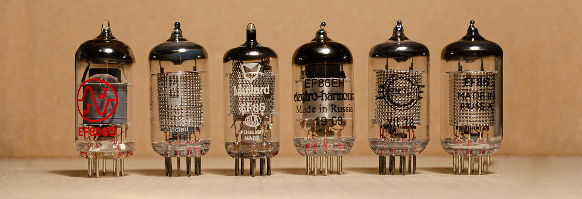
A few months later, while building additional Model 1955 amplifiers, I obtained more EF86 tubes: NOS examples and current-production examples, including tubes sold under the JJ Electronic, Electro-Harmonix and TAD Selected names. Repeating the same DC checks revealed a much larger spread than expected at the EL84 cathode.
This should not be read as a ranking of brands or as a simple NOS-versus-current-production problem. I have also measured meaningful differences between NOS EF86 tubes from the same manufacturer. The important point is that the result is sample-dependent and must be checked in the actual amplifier.
The unexpected measurement
The original Mullard operating point gives approximately 28 V at the EL84 cathode. With the original 560 ohm cathode resistor, Ohm’s law gives:
Ik = Vk / Rk = 28 V / 560 Ω = 0.050 A = 50 mA
The simplified circuit diagram shows how that current is divided: approximately 45 mA flows in the EL84 anode circuit and approximately 5 mA in the screen grid. The cathode resistor carries the sum, so the quantity calculated from the cathode voltage is total cathode current, not anode current alone.
With some EF86 samples installed, I measured approximately 40 V at the EL84 cathode:
Ik = Vk / Rk = 40 V / 560 Ω = 0.071 A = 71 mA
That is about 43% above the nominal 50 mA cathode current.
| Condition | Cathode resistance | Measured voltage | Calculated cathode current |
|---|---|---|---|
| Original Mullard operating point | 560 ohm | 28 V | 50 mA |
| High-current example observed | 560 ohm | 40 V | 71 mA |
At 50 mA, the 560 ohm resistor dissipates about 1.4 W. At 40 V and 71 mA, its dissipation rises to approximately 2.86 W, which is already very close to the rating of a 3 W resistor in a warm chassis.
Why excessive current matters
A single-ended output transformer carries standing DC current. Its air gap and core size are chosen for a particular operating range. Raising the quiescent current reduces the available flux swing before the core approaches saturation, especially at low frequencies. The likely results are reduced headroom and increased distortion.
The EL84 is also moved away from the operating point for which the load line, feedback and power-supply voltages were chosen. Depending on the actual anode and screen voltages, excessive current can increase tube dissipation and stress the output transformer, cathode resistor and power supply.
Before changing the bias network, confirm that the high reading is not being caused by a wiring error, an incorrect resistor, abnormal mains or HT voltage, or another circuit fault. EF86 variability is a strong influence in this topology, but it is not the only possible cause of an incorrect operating point.
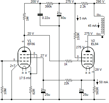
Figure 3. Mullard 3-3 operating voltages and EL84 currents. The 50 mA cathode current is the sum of approximately 45 mA anode current and 5 mA screen-grid current.
How the original DC feedback works
Mullard did not leave the two directly coupled stages completely unstabilised. The EL84 cathode is connected back to the EF86 screen grid through the 22 kilohm resistor. This creates negative DC feedback:
- If EL84 current rises, its cathode voltage rises.
- The EF86 screen-grid voltage then rises.
- EF86 anode current increases, producing a larger drop across its 1 megohm anode resistor.
- The EF86 anode voltage, and therefore the EL84 grid voltage, falls.
- The EL84 grid becomes more negative with respect to its cathode, opposing the original increase in current.
This is an elegant and essential part of the Mullard design. It reduces drift and helps stabilise both stages. It does not, however, have unlimited correction range.
The limitation of screen-grid feedback
The EF86 screen grid, g2, is much less effective at controlling anode current than the control grid, g1. The Mullard EF86 data sheet gives a control-grid-to-screen-grid amplification factor, μg1-g2, of approximately 38 at its stated characteristic point. In practical terms, a change of roughly 38 V at g2 is required to produce an effect comparable to a 1 V change at g1.
The exact relationship depends on the operating point, and the 3-3 runs the EF86 under unusual low-voltage conditions. The data-sheet figure should therefore be treated as an indication rather than an exact loop-gain calculation for this circuit. Nevertheless, it explains the basic limitation: the screen-grid feedback path can correct moderate drift, but its control authority per volt is relatively weak.
If the installed EF86 is close to the population around which the original circuit was developed, the loop can keep the EL84 near the intended operating point. If the EF86 falls far enough outside that range, the EL84 cathode voltage can still move substantially.
Tube selection works, but it is not a robust solution
With a batch of EF86 tubes available, it is possible to measure each sample and select one that produces approximately 28 V across the original 560 ohm cathode resistor. This is acceptable during development, restoration or bench testing.
It is not a satisfactory long-term solution for a customer amplifier. The EF86 may eventually be replaced, and the replacement may shift the EL84 operating point even if it is new, NOS, tested or sold as a selected tube. The bias should therefore be checked whenever the EF86 is changed, and the amplifier should provide a practical means of correction if tube substitution is expected.
A useful historical precedent: BBC AM8/2 and AM8/2A
A closely related professional implementation appears in BBC Instruction S.3, Section 10, for the AM8/2 and AM8/2A loudspeaker amplifiers.
For serial numbers 101 to 185, the BBC circuit retains direct coupling between the EF86 and EL84 stages. The EL84 cathode-bias resistance is not a single 560 ohm resistor. It uses 560 ohm plus 150 ohm in series, for a total of 710 ohm. The document specifies approximately 36 V across the two resistors:
Ik = Vk / Rk = 36 V / 710 Ω = 0.0507 A = 50.7 mA
This is essentially the same target cathode current as the Mullard circuit, but obtained at a higher cathode voltage and with a higher total resistance.
The BBC document does not state that the added resistance was introduced specifically to compensate for EF86 sample variation, so it should not be presented as proof of that cause. It is nevertheless a useful historical precedent: a professional direct-coupled derivative of the 3-3 did not treat 560 ohm as an inviolable value.
For serial numbers 186 to 505, the documented BBC design changed to AC coupling between the stages and used different bias and feedback arrangements. At that point it was no longer an exact Mullard 3-3 topology, even though it remained a related EF86/EL84 amplifier.
Recommended practical approach
The main rule is simple: do not assume the bias is correct because the schematic and component values are correct. Measure the amplifier with the actual EF86 and EL84 installed.
- Verify the wiring, resistor values, HT supply and ground connections before modifying the circuit.
- Allow the amplifier to reach thermal stability.
- Measure the EL84 cathode voltage with respect to chassis or 0 V.
- Calculate total cathode current from Ik = Vk / Rk
- With the original 560 ohm resistor, the nominal target is approximately 28 V, corresponding to 50 mA total cathode current.
- If the current is substantially high, increase the cathode-bias resistance and repeat the measurement.
- Recheck the operating point whenever the EF86 is replaced.
A fixed correction can be made by adding a resistor in series with the original 560 ohm part. A value around 150 ohm is a useful starting point and has the BBC precedent described above, but the final value should be determined by measurement in the individual amplifier.
A more flexible solution is a suitably rated 200 ohm wirewound trimmer or adjustable resistor in series with the original 560 ohm resistor.
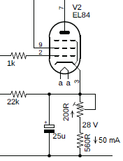
Figure 4. EL84 cathode-bias trimmer in series with the original 560 ohm resistor. Adjust for 28 V across the 560 ohm resistor.
With the arrangement shown, adjust the trimmer until the voltage measured across the fixed 560 ohm resistor is approximately 28 V. This sets the current through the whole series network to approximately 50 mA.
Important: 28 V is the target only when the measurement is made across the 560 ohm resistor. If the meter is connected from the EL84 cathode to ground, it measures the voltage across the total cathode resistance. The correct target is then:
Vk(total) = 0.050 A × Rtotal
For example, 710 ohm at 50 mA gives approximately 35.5 V.
| Cathode network | Meter connection | Target reading |
|---|---|---|
| 560 ohm only | EL84 cathode to ground | 28 V |
| 560 + 150 ohm | Across the 560 ohm resistor | 28 V |
| 560 + 150 ohm | EL84 cathode to ground | 35.5 V |
The cathode bypass capacitor should remain connected across the complete cathode-resistance network, and its voltage rating must be adequate for the resulting cathode voltage. Use at least a 50 V part; a 63 V rating is preferable where space permits, because the circuit may operate in the mid-30-volt range or higher during testing.
Resistor and trimmer power rating
If a 200 ohm adjustable resistor carries 50 mA and is set to its full resistance, its dissipation is:
P = I2 R = (0.05 A)2 × 200 Ω = 0.5 W
A 1 W part is a prudent minimum; additional margin is preferable in a warm tube-amplifier chassis. Use a component specifically suitable for rheostat service, and do not substitute a small low-power preset trimmer.
The original 560 ohm resistor dissipates about 1.4 W at 50 mA, which explains the use of a 3 W part. Any added fixed resistor must also be rated with margin. A 150 ohm series resistor dissipates approximately 0.375 W at 50 mA, so a 1 W part is a sensible minimum.
After adjustment, verify the cathode current again at full operating temperature and confirm that the EL84, output transformer, bypass capacitor and power supply remain within their ratings.
Conclusion
The EL84 bias variation observed in the Mullard 3-3 is not necessarily a wiring mistake or a defective output tube. It is a consequence of combining direct coupling with normal EF86 sample variation and relying on a screen-grid DC feedback path whose corrective authority is limited.
The original Mullard design remains elegant and historically important. Exact or near-exact replicas should nevertheless be treated as measured circuits, not as assemblies whose operating point is guaranteed by nominal component values alone. Verify the EL84 cathode current with the actual EF86 installed, then adjust the cathode-bias resistance when required. This keeps the amplifier closer to its intended operating point and reduces the risk of unnecessary distortion, excessive current and output-transformer stress.
References and related reading
- Mullard, “Three-watt Amplifier”, original 3-3 circuit description and DC conditions: https://www.r-type.org/articles/art-003h.htm
- Mullard EF86 data sheet, including mu(g1-g2) = 38: https://www.r-type.org/pdfs/ef86.pdf
- BBC Instruction S.3, Section 10, Loudspeaker Amplifiers AM8/2 and AM8/2A: https://primary-audio.com/articles/AM8_2.pdf
- Heated Cathode, Model 1955 / Mullard 3-3 overview: https://www.heatedcathode.com/3w-single-ended-class-a-stereo-tube-amplifier/
- Heated Cathode, Model 1955 measurements: https://www.heatedcathode.com/3w-single-ended-class-a-stereo-tube-amplifier/measurements/