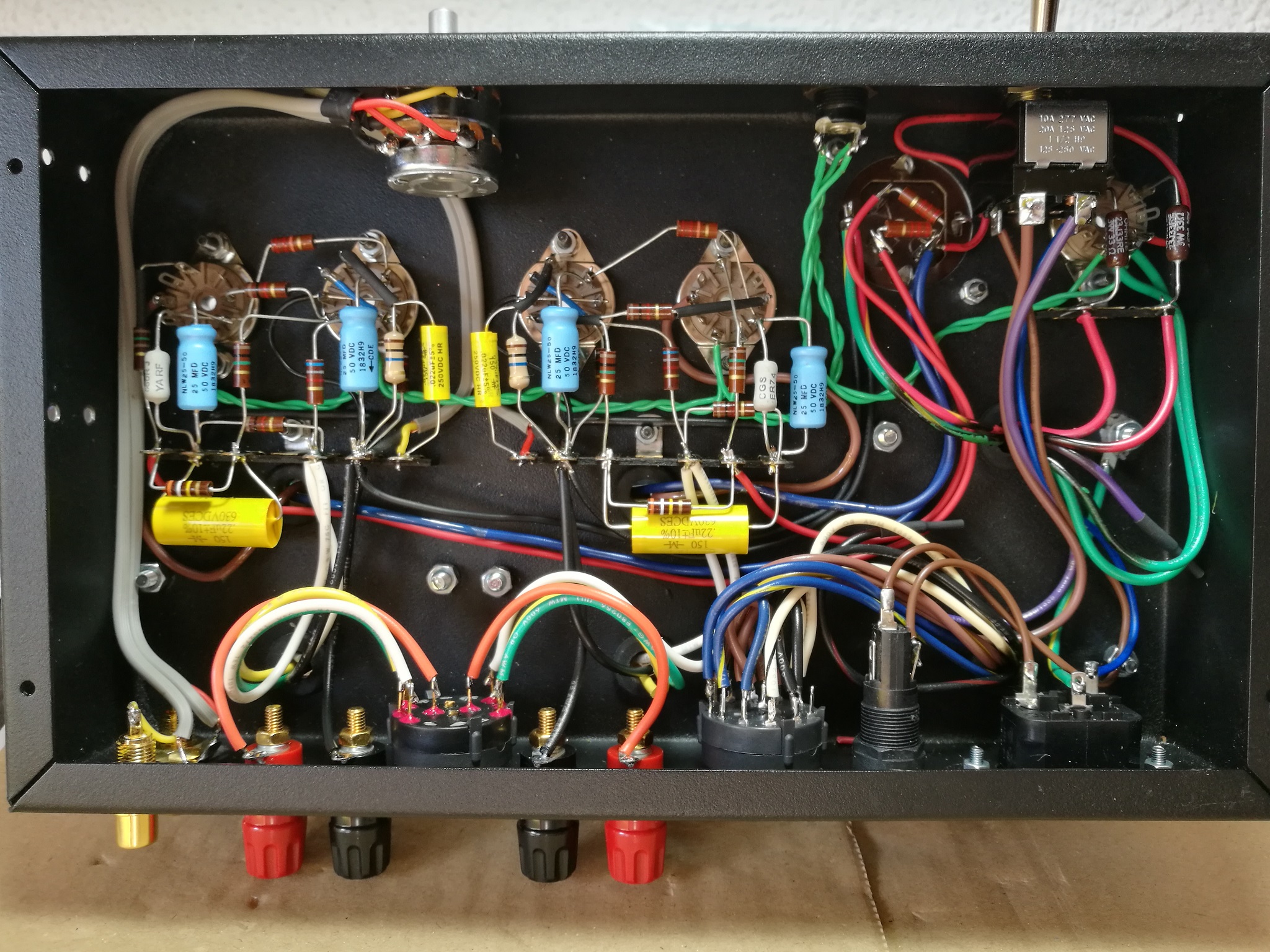
This document aims to serve as a guide for building the 1955 Gen2 vacuum tube amplifier. It is the reference I myself follow for assembling these units, and it is also the documentation that others have used to assemble the amplifier kit.
It can also be used for assembling the simplified wiring version, the 1955 Gen1, which only differs from the Gen2 in that it lacks impedance and voltage switching. Apart from these differences, the assembly and connection of all other components are identical in both models.
Estimated assembly time 13 hours.
(v1.2-en) March 19, 2022
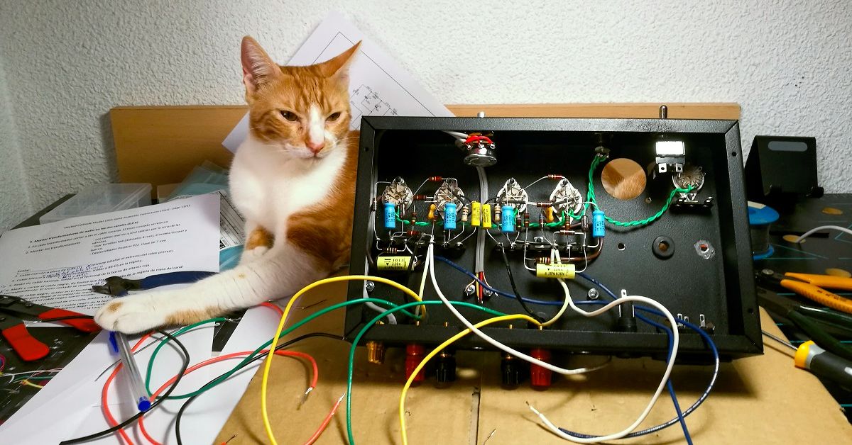
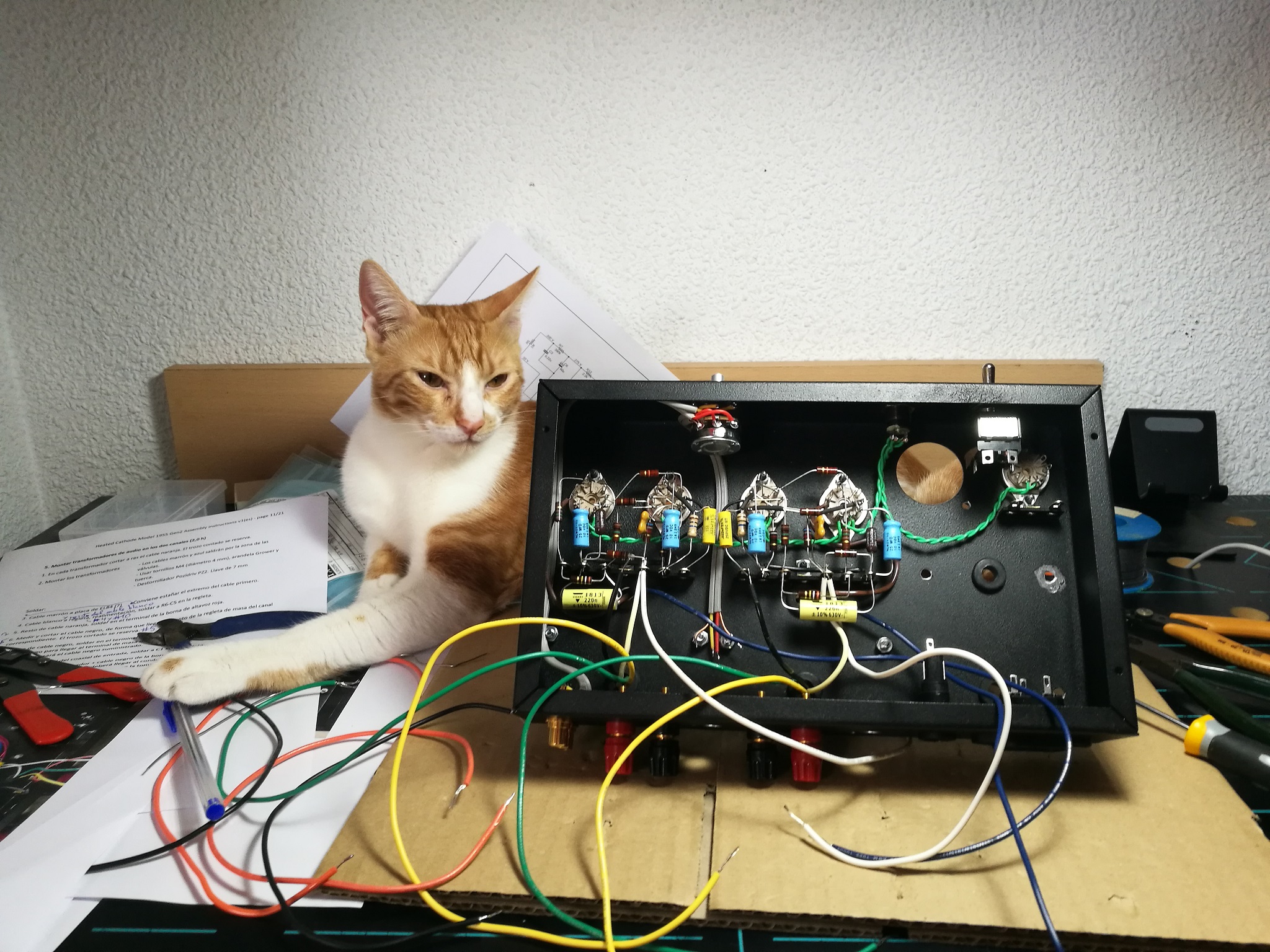
NOTES: Some photos do not correspond to the assembly sequence, the text of which has been modified after taking the photos to facilitate assembly. You must always follow written instructions. It is essential to have the circuit diagram on hand to identify the pins of the tubes sockets and their components.
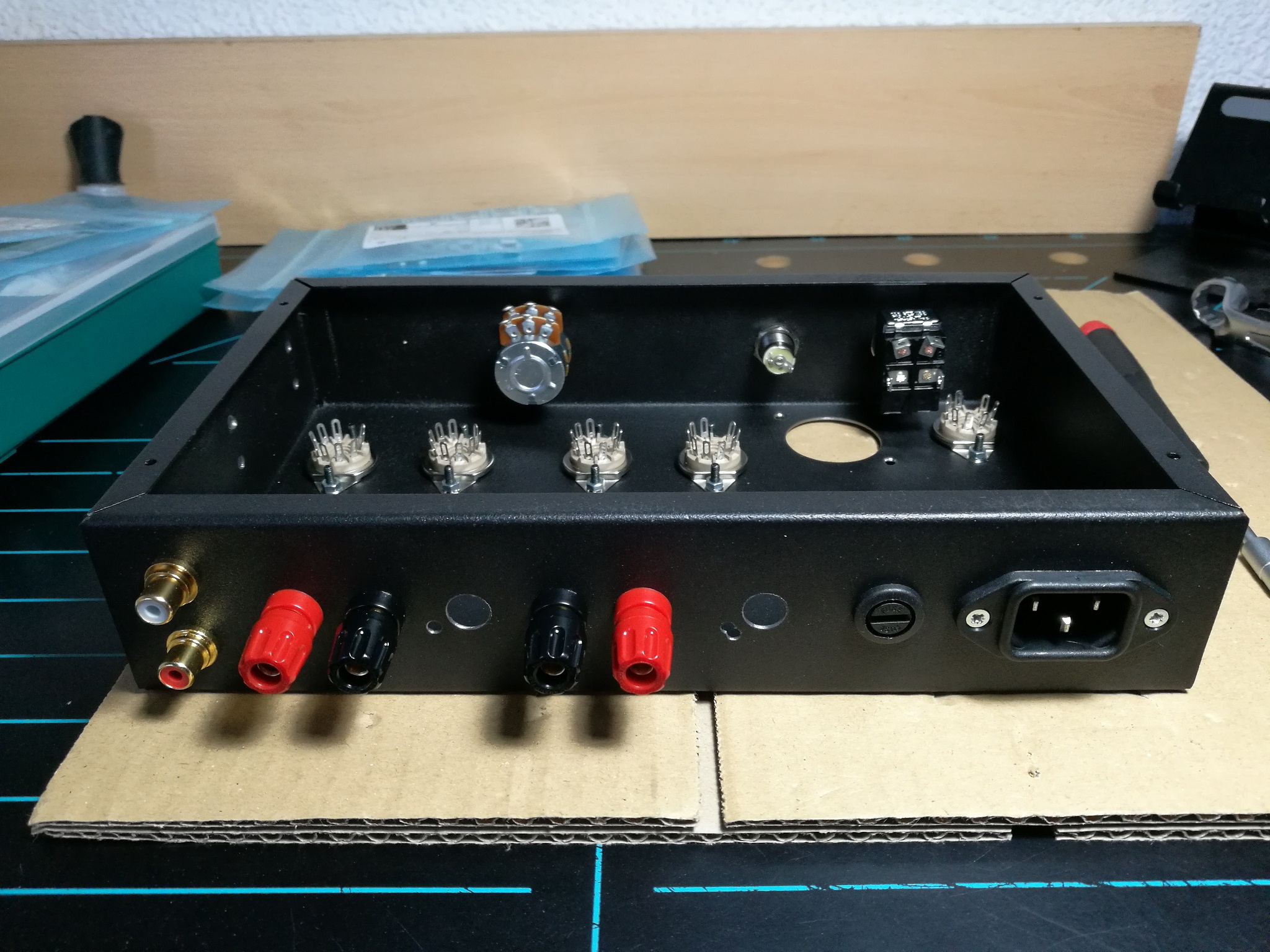
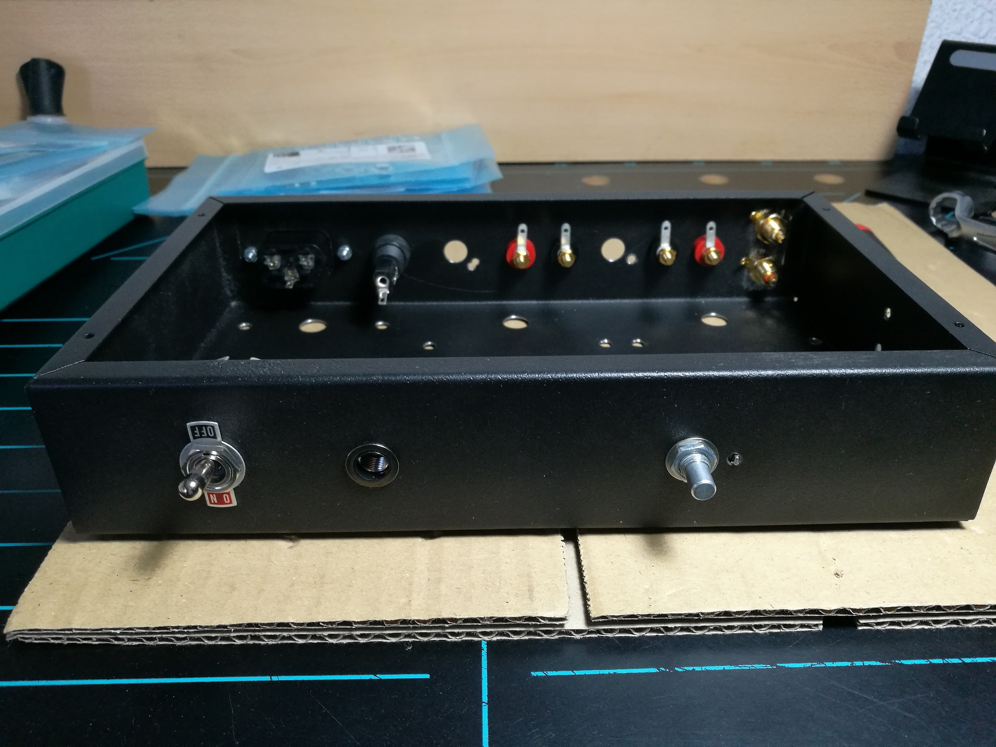
1. Chassis mount (3.0 h)
Always work on a piece of cardboard to avoid damaging or scratching the chassis.
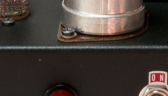
1.1.- Power switch
- Use a 14 mm wrench (tube) by hand. Be careful not to scratch the ON-OFF plate.
1.2.- Pilot lamp holder
- Use a 15 mm wrench (star).
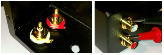
1.3.- RCA input connectors
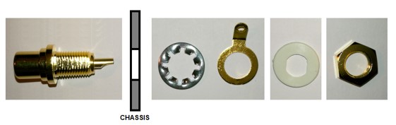
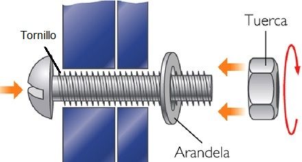
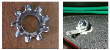
- Order: connector, chassis, M8 star washer, terminal, plain plastic washer, nut. The red connector will be on chassis top. Use a 12 mm wrench (star).
The toothed washer must pierce the chassis paint to ensure earth return contact with the chassis. To test this, you will need to measure the continuity between the two input connectors.
1.4.- Potentiometer
- Order: potentiometer, M8 star washer, chassis, plain washer, nut. Use a 11 mm wrench (tube).
1.5.- Fuse holder
- Use a 14 mm wrench (star).
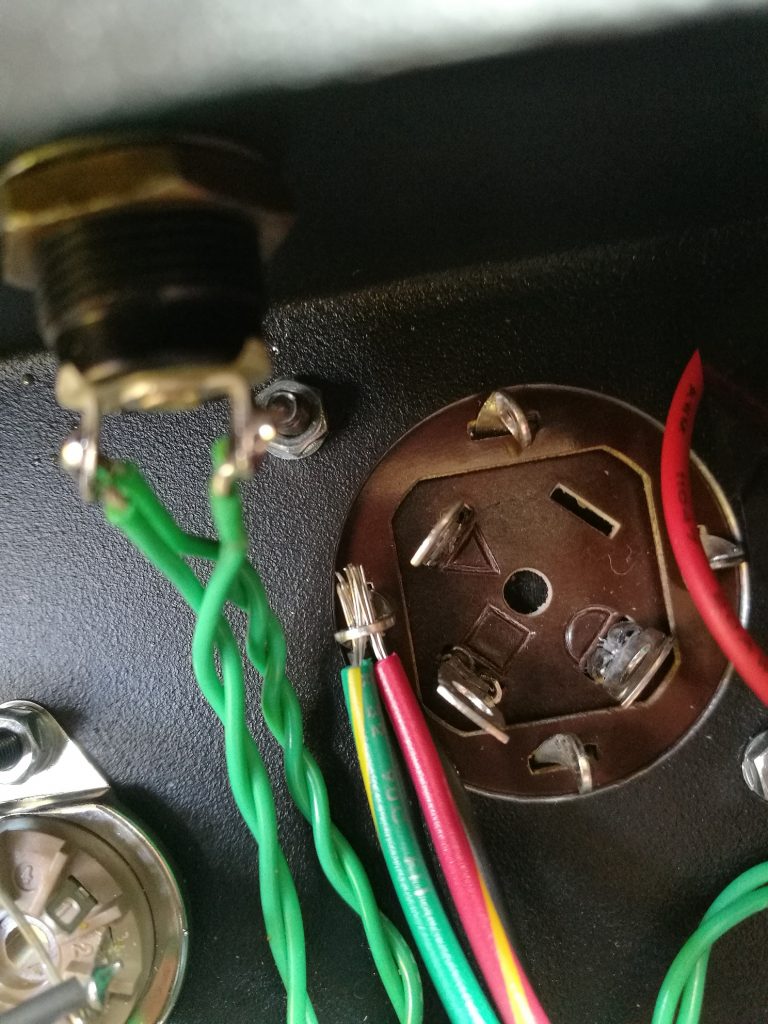
1.6.- Power connector
- M3 Cone Head (Countersunk) screws, star washer and nut. Use a PH1 screwdriver and a 5.5 mm wrench.
1.7.- Speaker output connectors
- Terminal, split washer (Grower) and single nut. Use a 7 mm wrench. Don’t forget to align the holes.
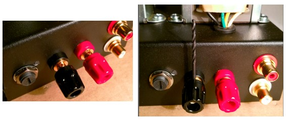
The speaker connectors have a hole to optionally insert the speaker wires. You can use a trick to align the holes vertically with a 2 mm drill bit by rotating and holding the connector into vertically correct position before tightening the nut.
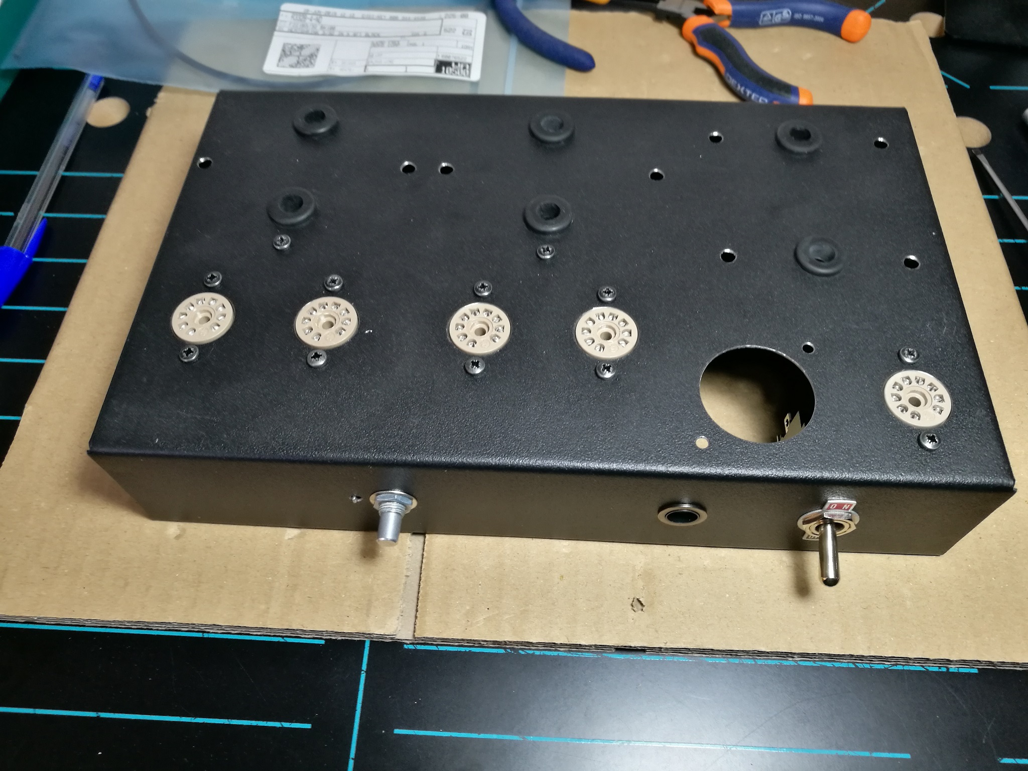
1.8.- Valve sockets
- M3 black screws, tooth washer and nut. Use a PH1 screwdriver and a 5.5 mm wrench. Do not forget the terminal strip on the rectifier valve socket.
1.9.- Terminal strips
- M3 black screws, tooth washer and nut.
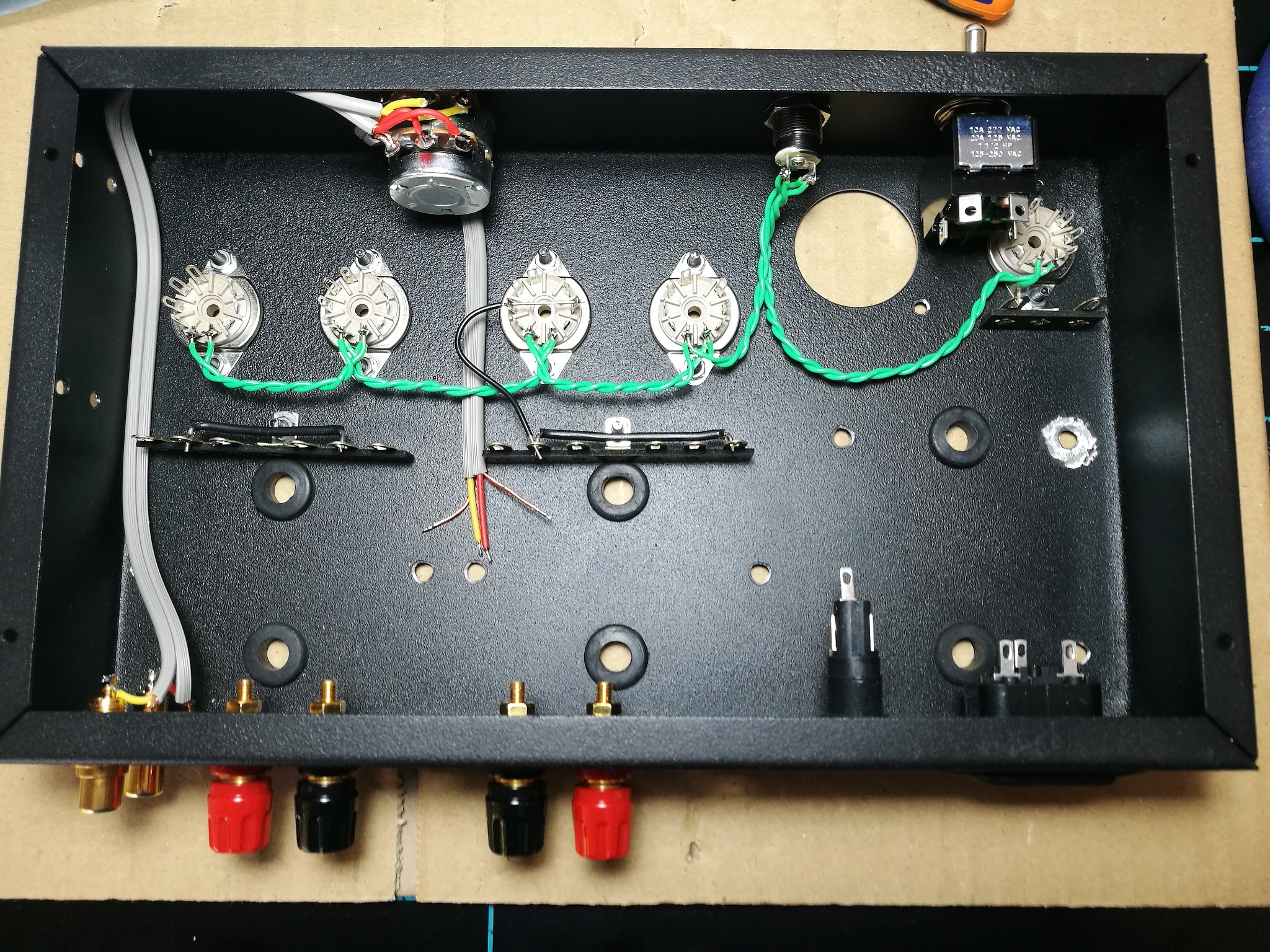
1.10.- Rubber grommets
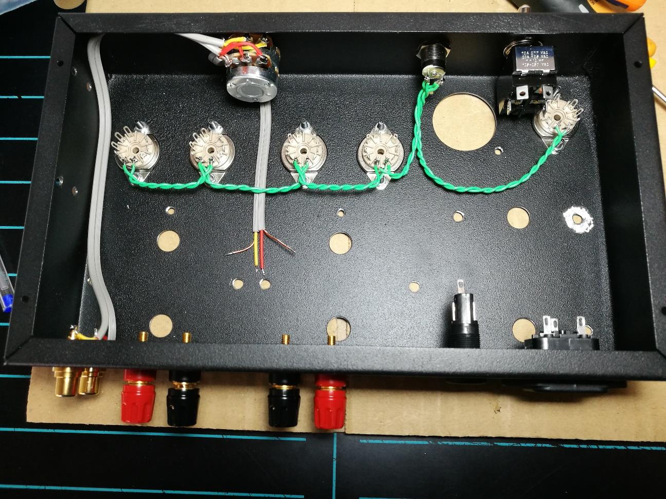
1.11.- Wire and solder the valve filament circuit with 0.5 mm2 (20 AWG) green wire. The threads must be twisted 2x 45 cm, cut at 15, 7, 7.5 and 7 cm. Pins 4 and 5, and pilot lamp holder. Do not weld on the rectifier valve socket.
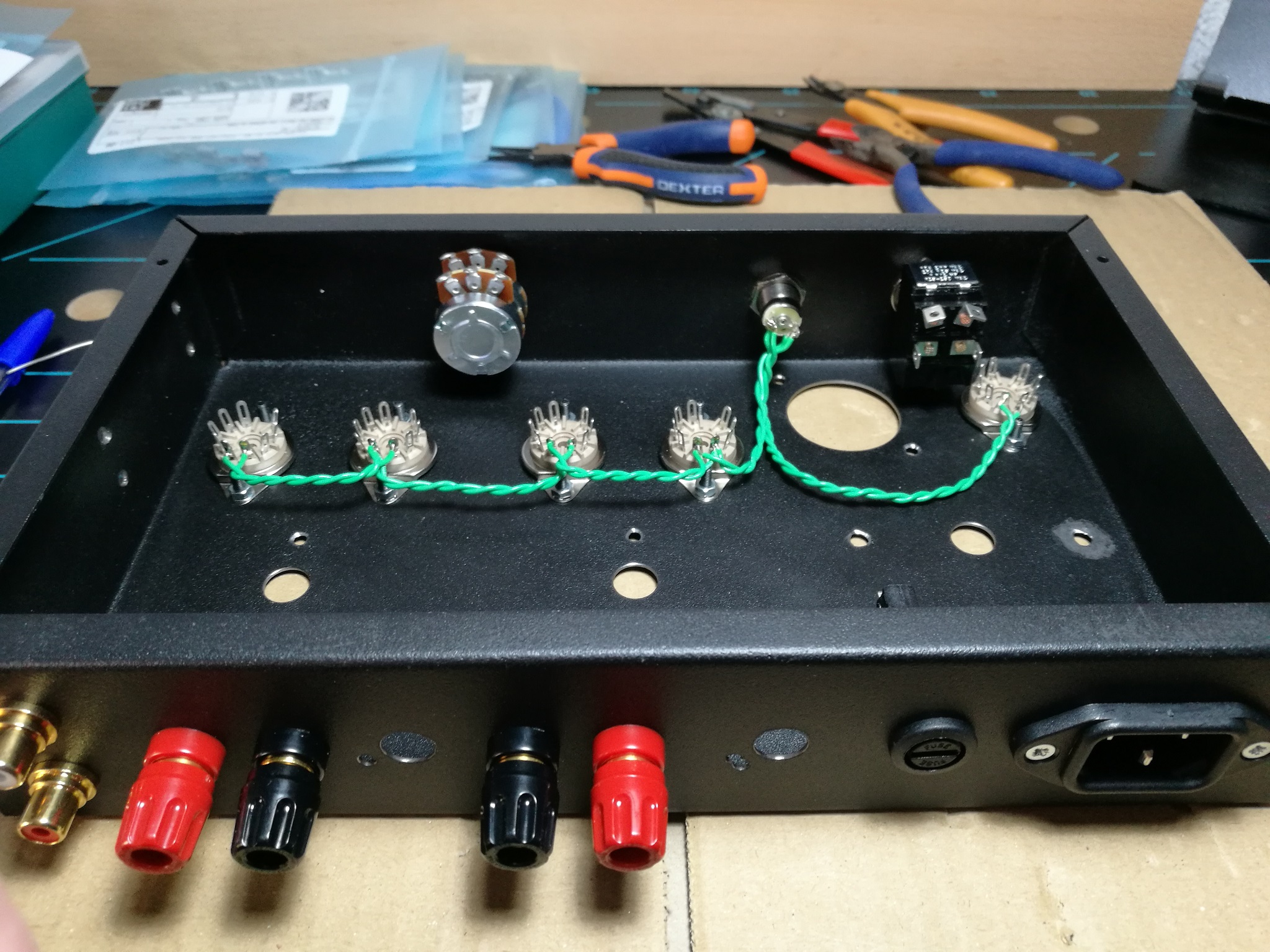
1.12.- Connect the double coaxial cable (45 cm for the two sections) to the input connectors and to the potentiometer. The red wire for the right channel to the red connector (red – right).

1.13.- Make two ground bridges with 1 mm2 (17 AWG) black wire.
- length 70 mm peel 10 mm at each end, bend to 10, 50, 10 mm.
- length 60 mm peel 10 mm at each end, bend to 10, 40, 10 mm.
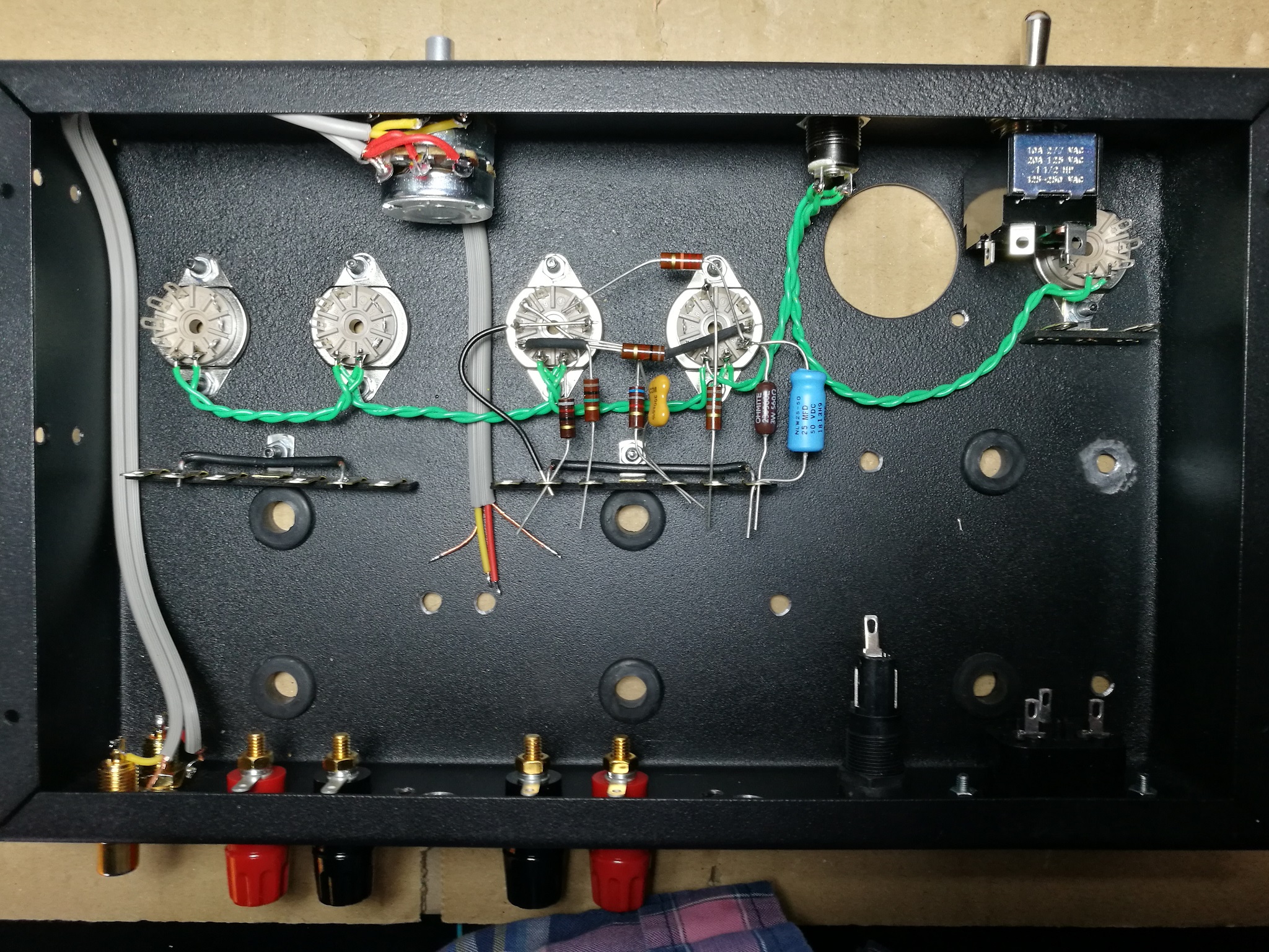
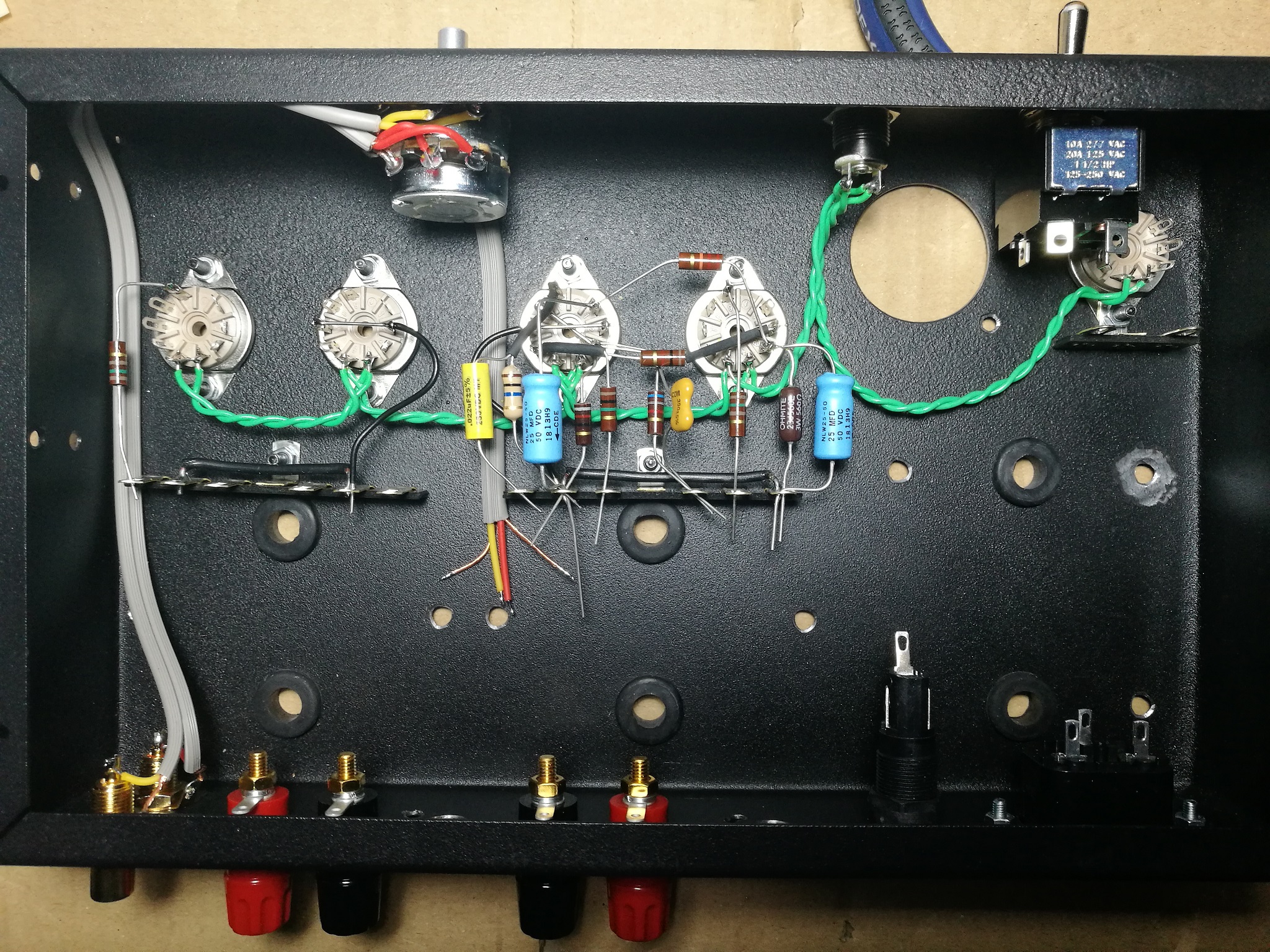
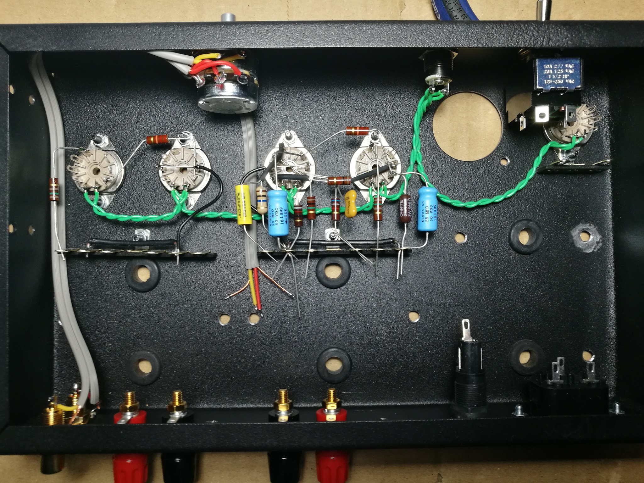
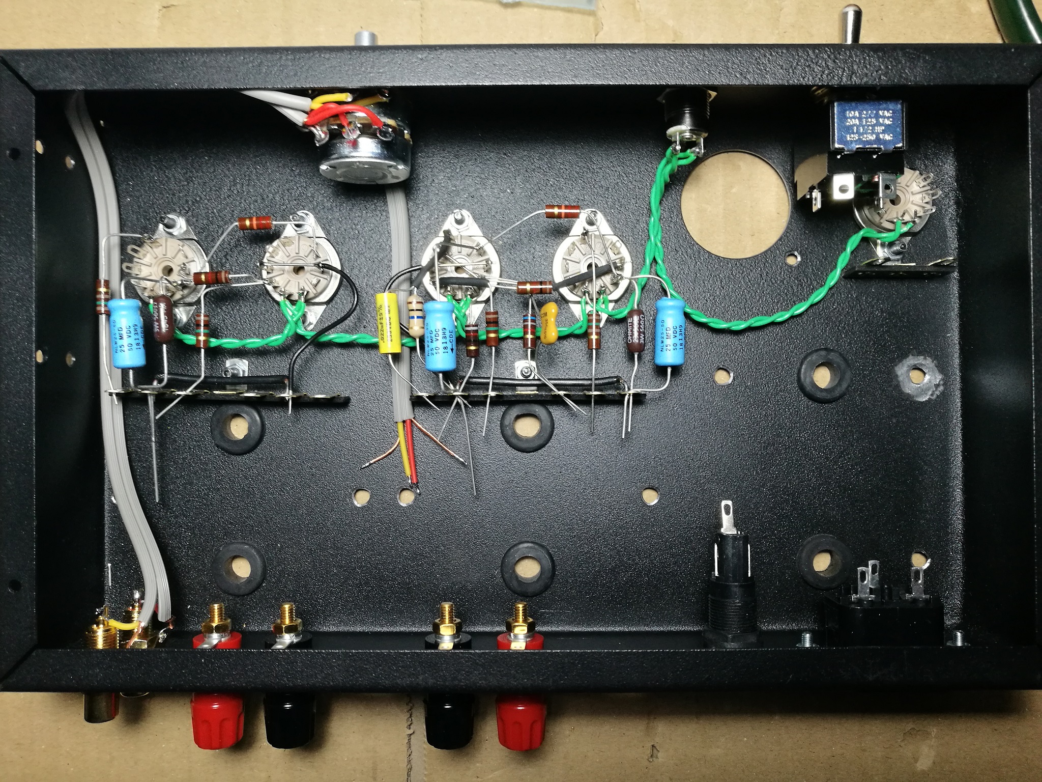
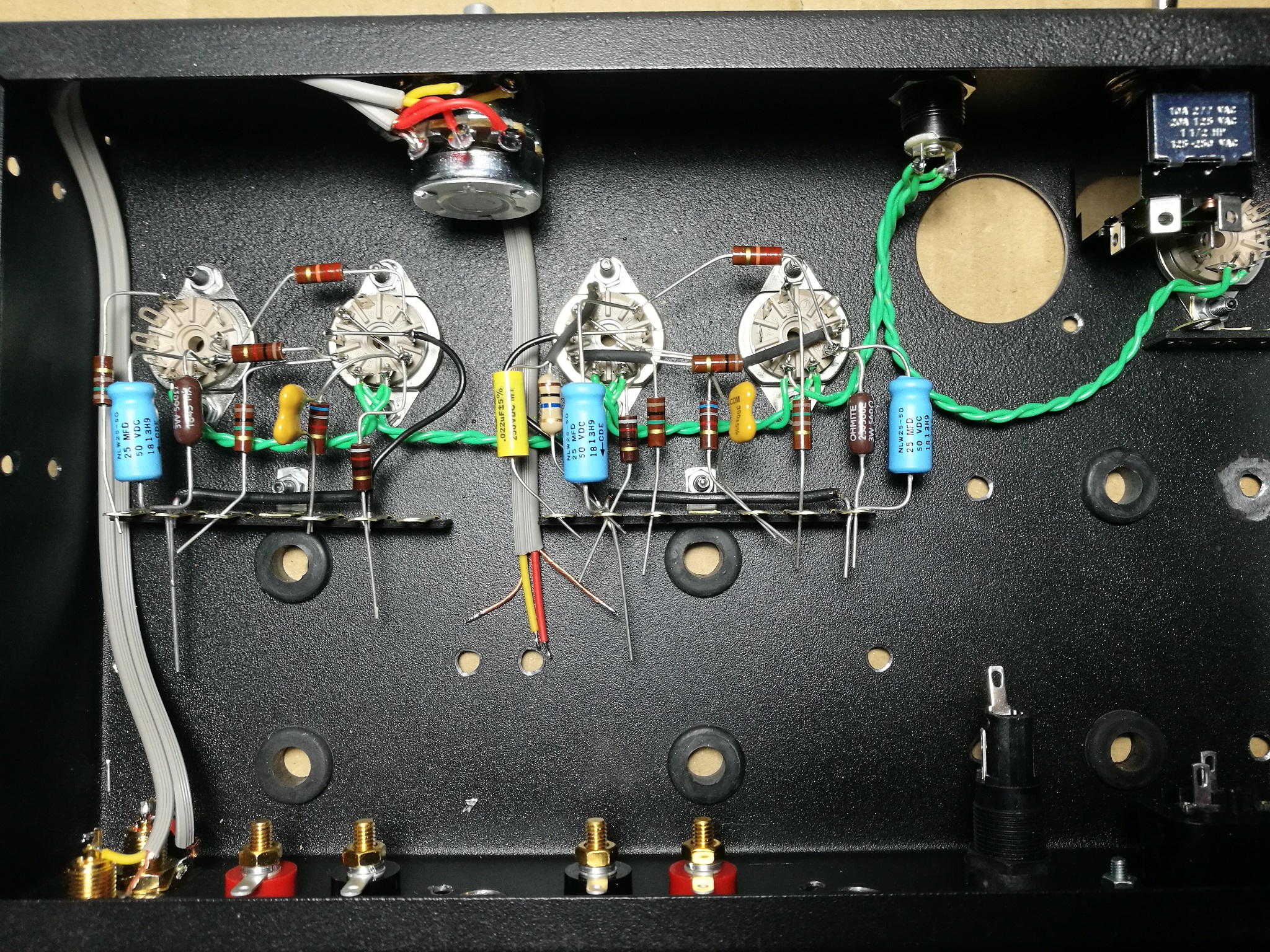
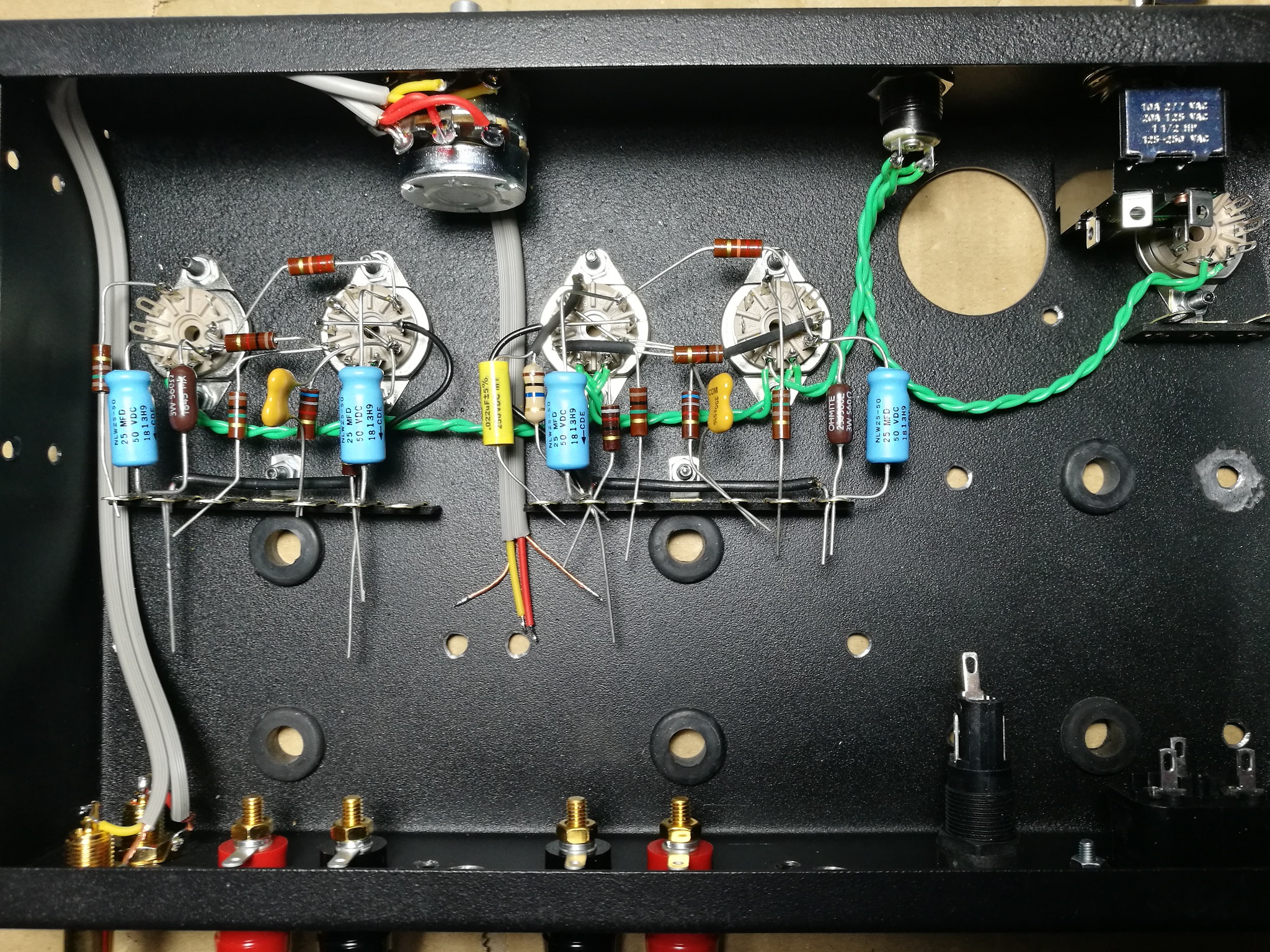
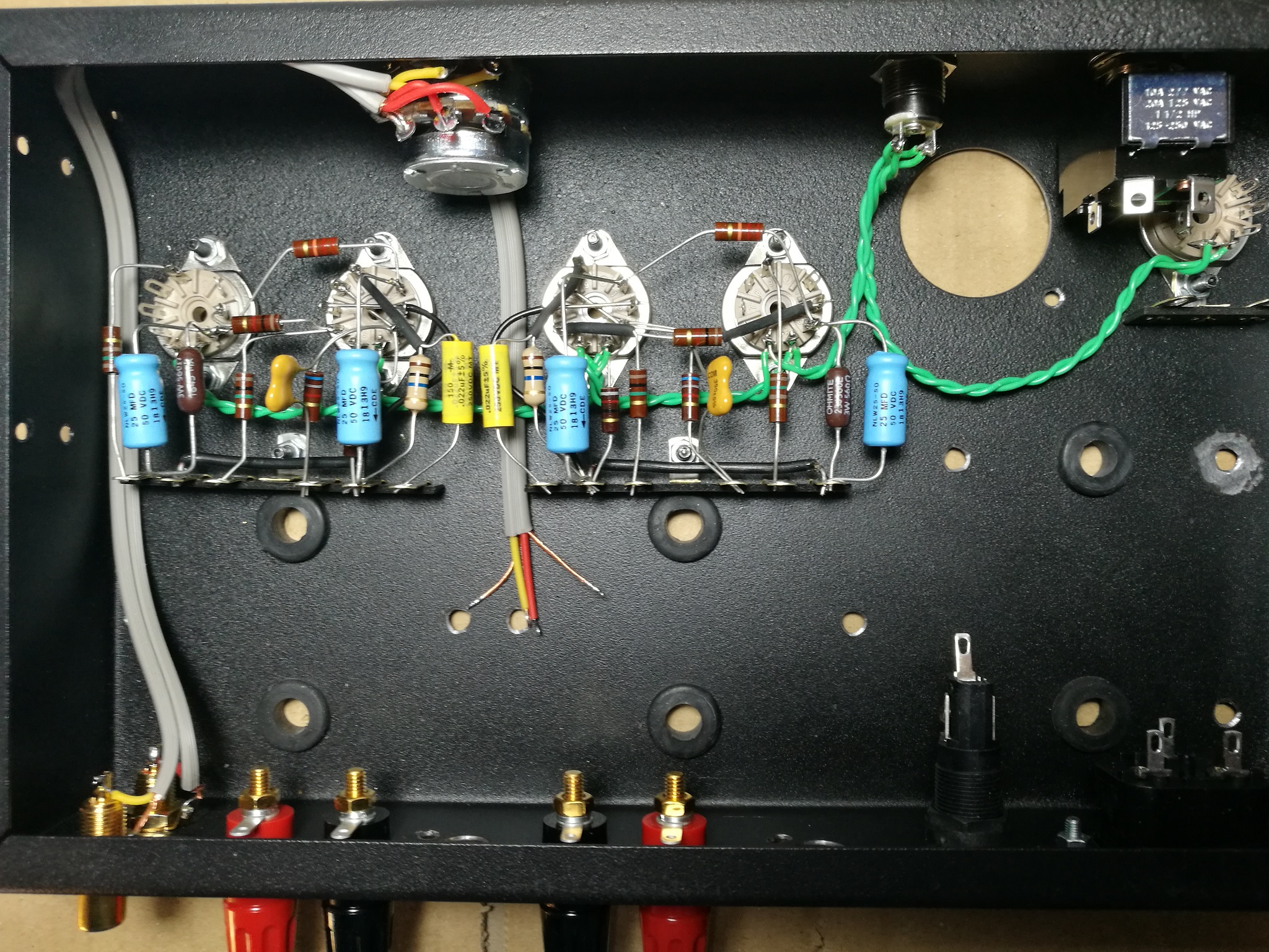
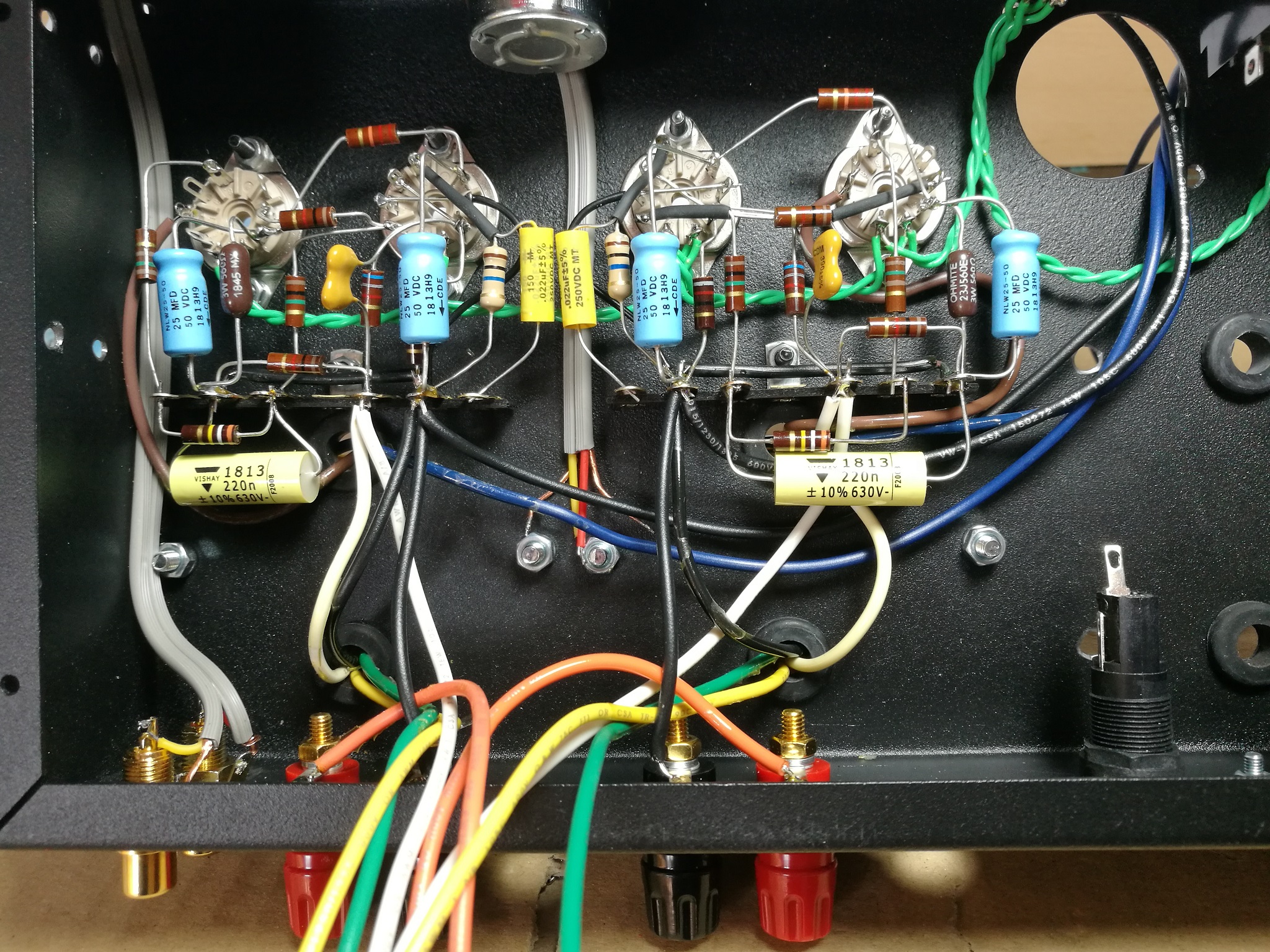
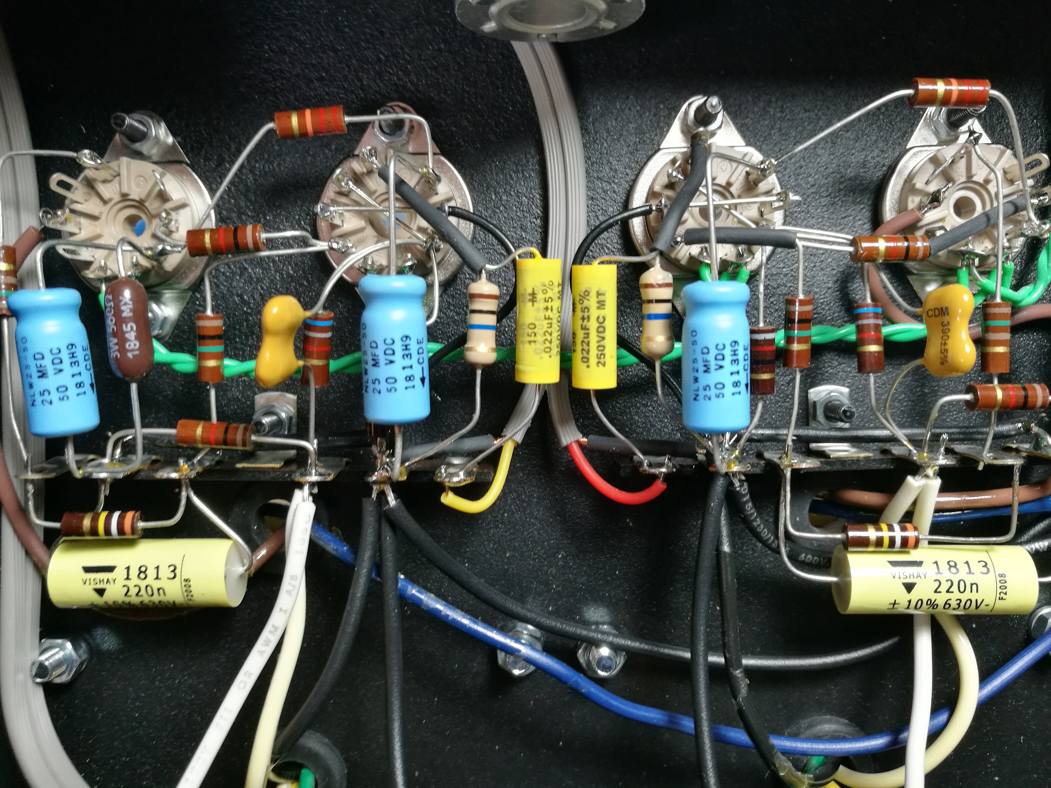
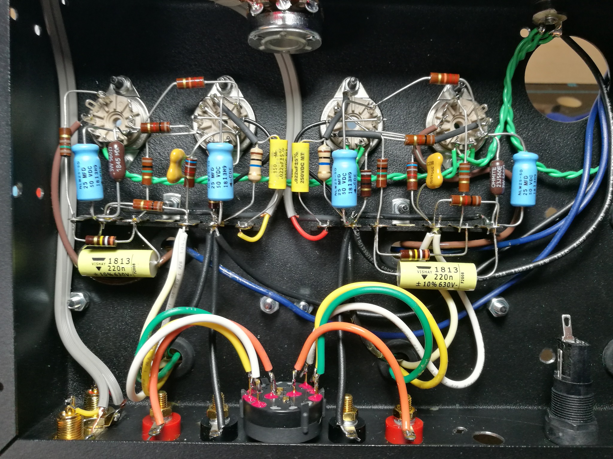
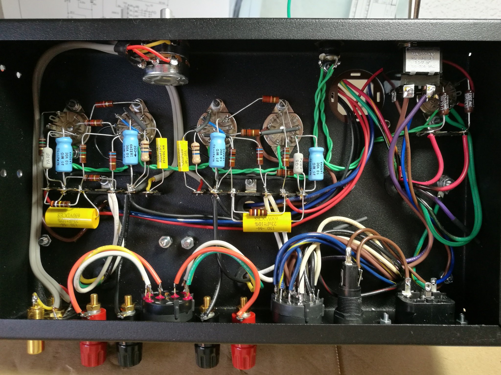
2. Solder right channel components to valve sockets (not on terminal strip) (1,5 h)
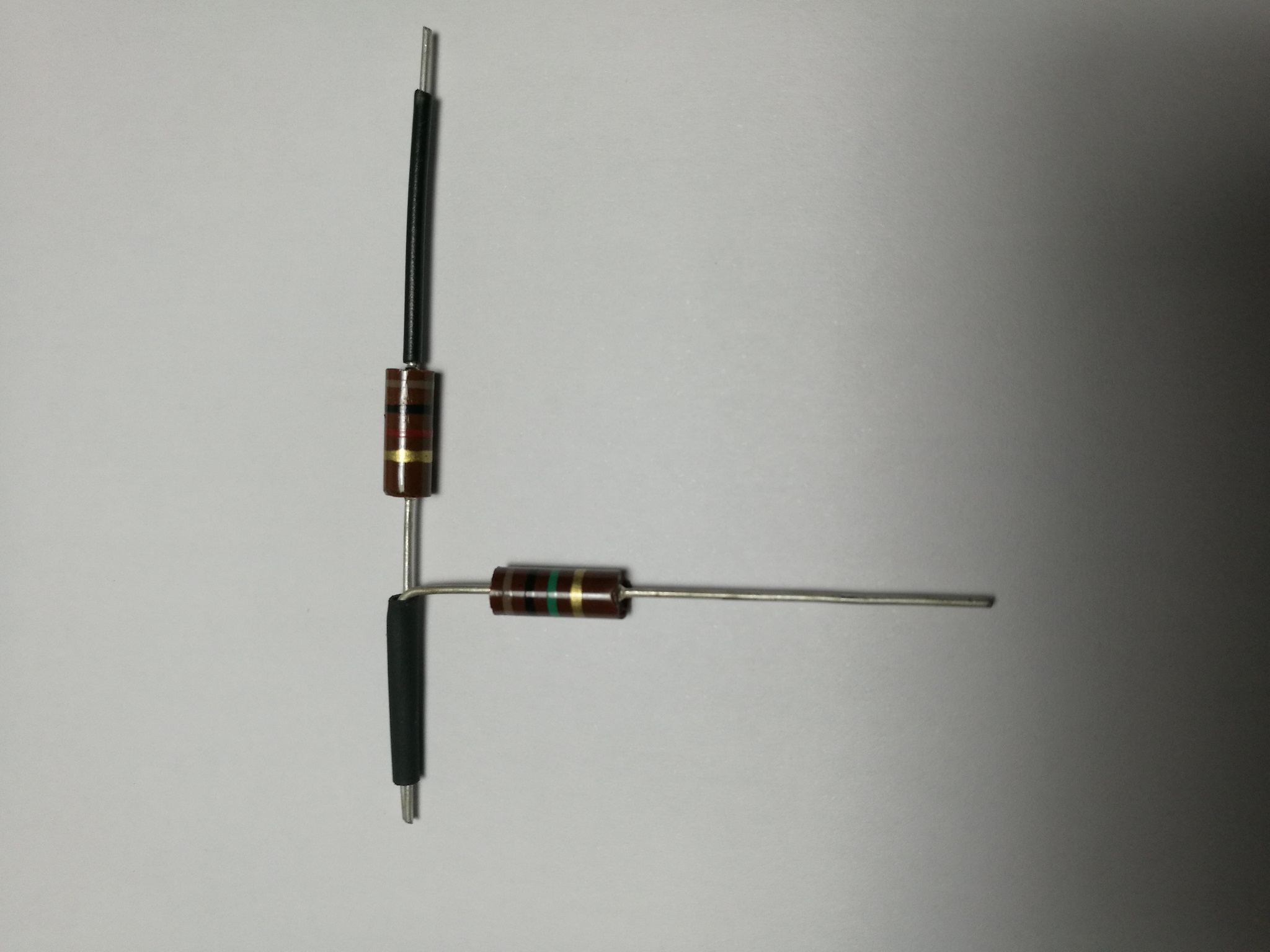
Use heat shrinkable black sleeve to avoid contact, as you can see in the pictures.
2.1.- 0.5 mm2 black wire in EF86 (2 – 7 – GND) length 75 mm and strip 20 and 5 mm, solder it on top of the socket pin hole.
2.2.- C8, R13, R9 (25 uF, 560/700R, 22k)
2.3.- R10 (150R)
2.4.- 0.5 mm2 black wire on EF86 (3 – 8) and R4, R6, C5 (82R, 6k8, 390p) strip 20 mm and weld on leg 8, solder it to the bottom of the socket pin hole that does not touch the other wire previous welded.
2.5.- R8, R5 (1k, 1M) isolate the two resistors joints between them.
2.6.- C4 (25 uF)
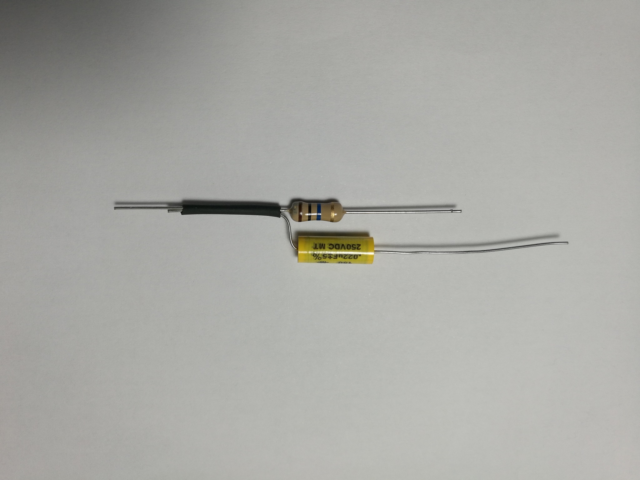
2.7.- R3, C1 (10M, 0.022u)
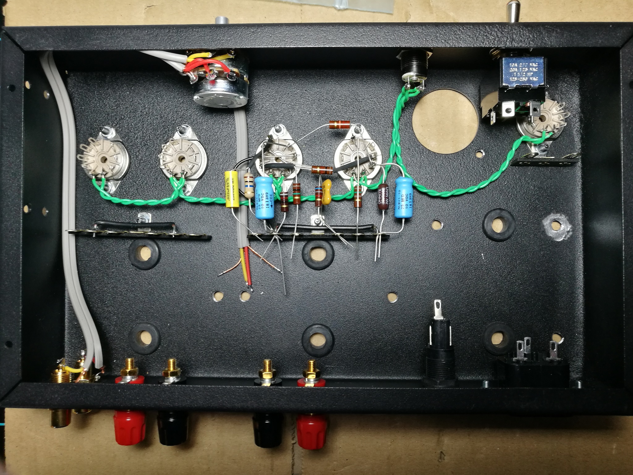
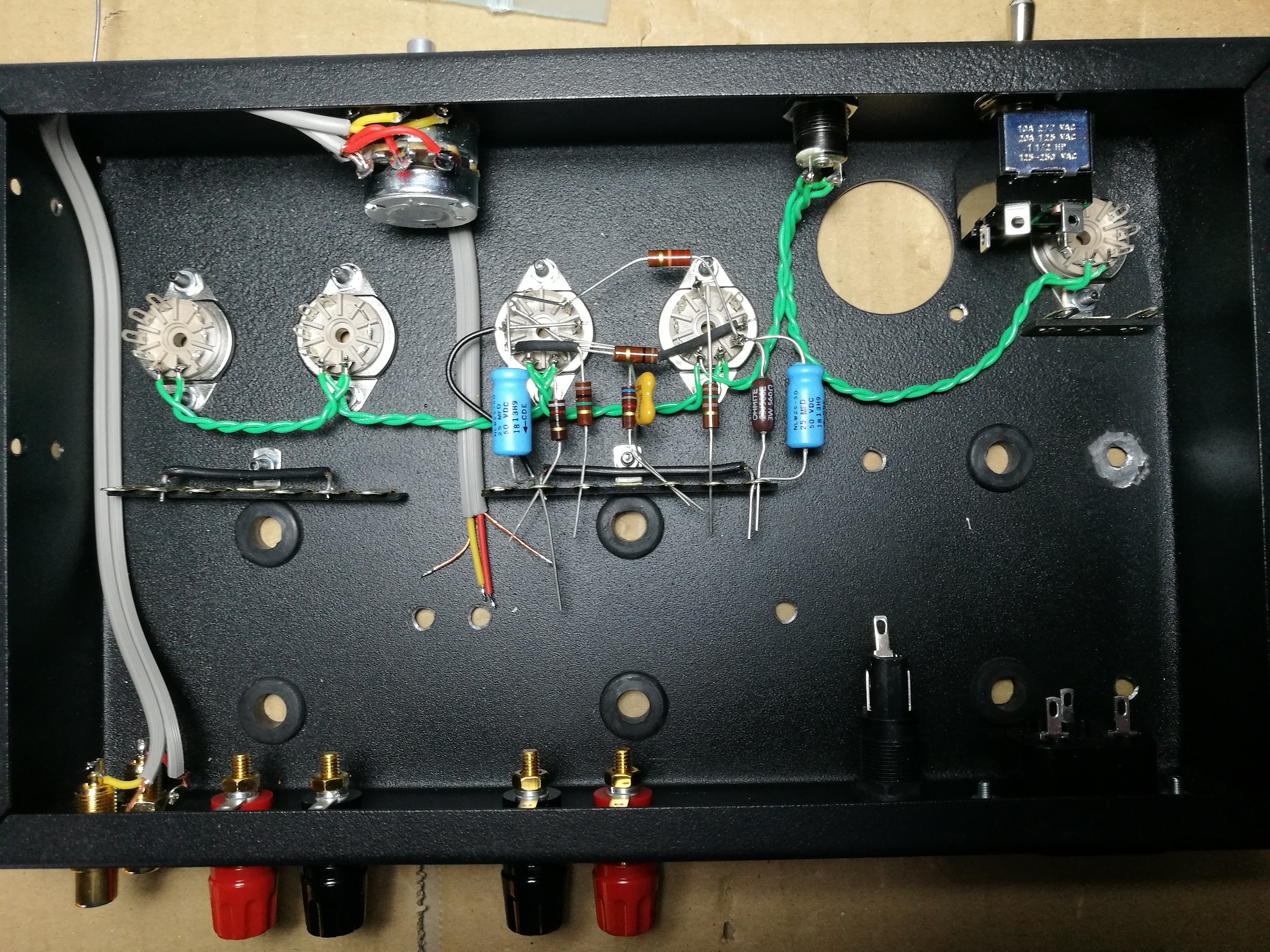
3. Solder left channel components to valve sockets (not on terminal strip) (1,5 h)
Use heat shrinkable black sleeve to avoid contact, as you can see in the pictures.
3.1.- 0.5 mm2 black wire on EF86 (2 – 7 – GND) length 75 mm and strip 20 and 5 mm, solder it on top of the socket pin hole.

3.2.- R10 (150R)

3.3.- C8, R13, R9 (25uF, 560/700R, 22k)
3.4.- R8, R5 (1k, 1M)
3.5.- 0.5 mm2 black wire on EF86 (3 – 8) and R4, R6, C5 (82R, 6k8, 390p) strip 20 mm and weld on leg 8, cut once welded, solder it to the bottom of the socket pin hole that does not touch the other wire previous welded.
3.6.- C4 (25uF)
3.7.- R3, C1 (10M, 0.022u)
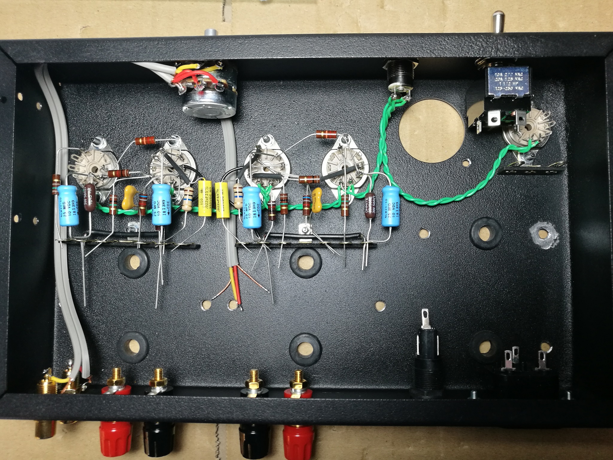
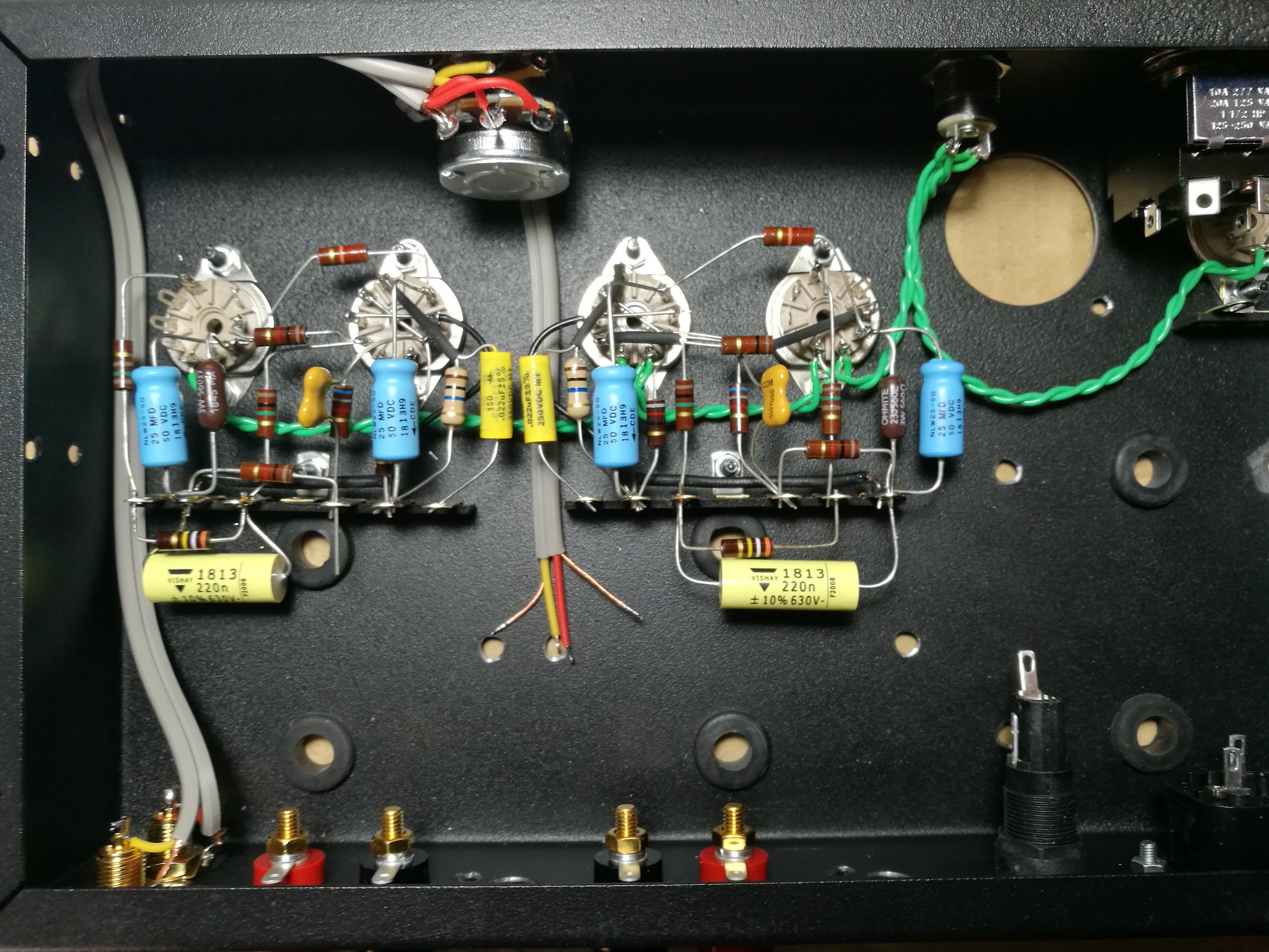
4. Assemble and weld on the terminal strips of the two channels (1,5 h)
To weld on valve sockets, terminals and switchs sockets, a 15W soldering iron is sufficient. For terminal blocks and other “thick” mounting points, it is advisable to use a 30W soldering iron.
4.1.- Cut the legs of the protruding components on the terminal strips.
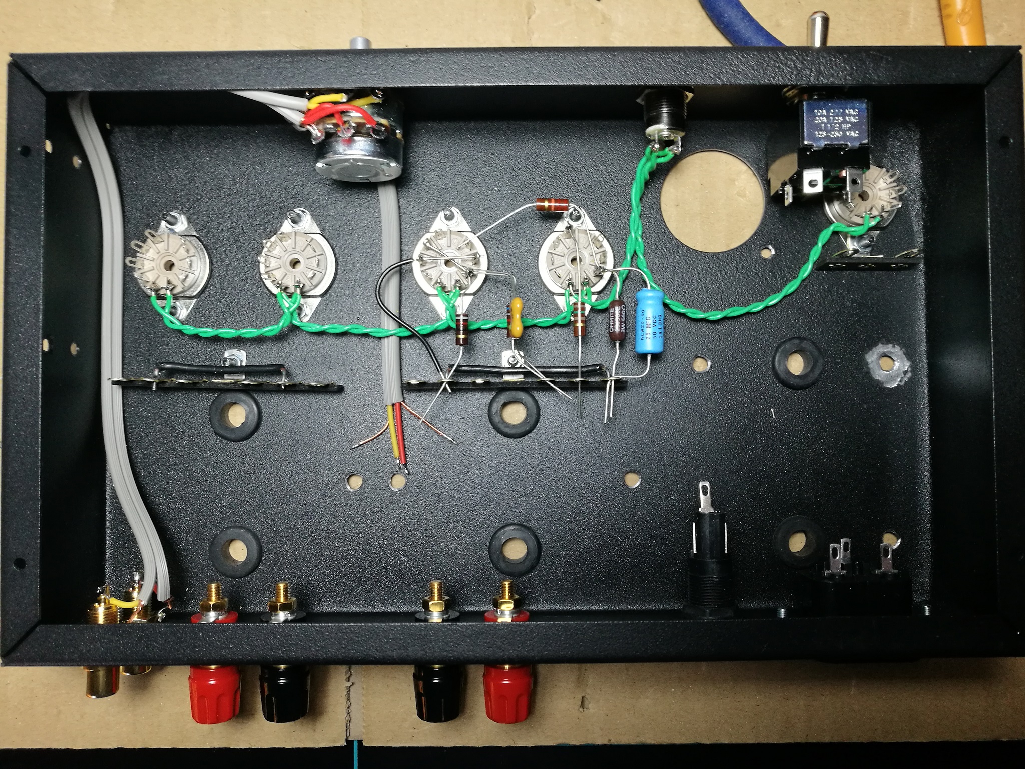
4.2.- R7, C3 (390k, 0.22u) and solder terminal strips pins # 3 and # 9. (Counting terminal strips pins from left to right from 1 to 12)
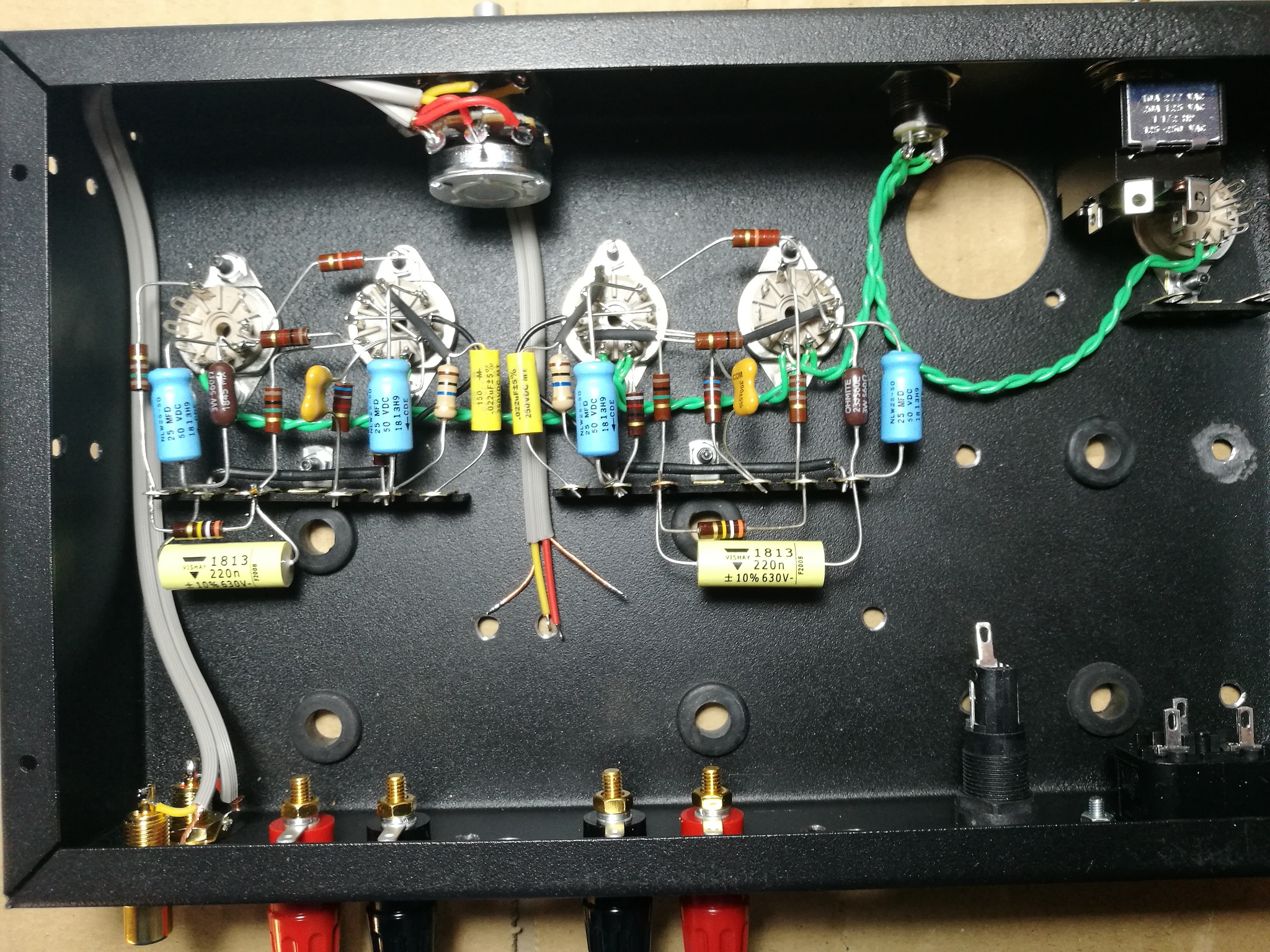
4.3.- R14 (1k)
4.4.- Solder terminal strips pins # 2 and # 12.
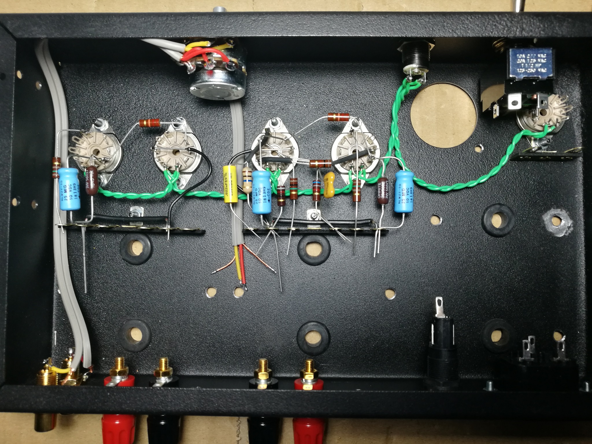
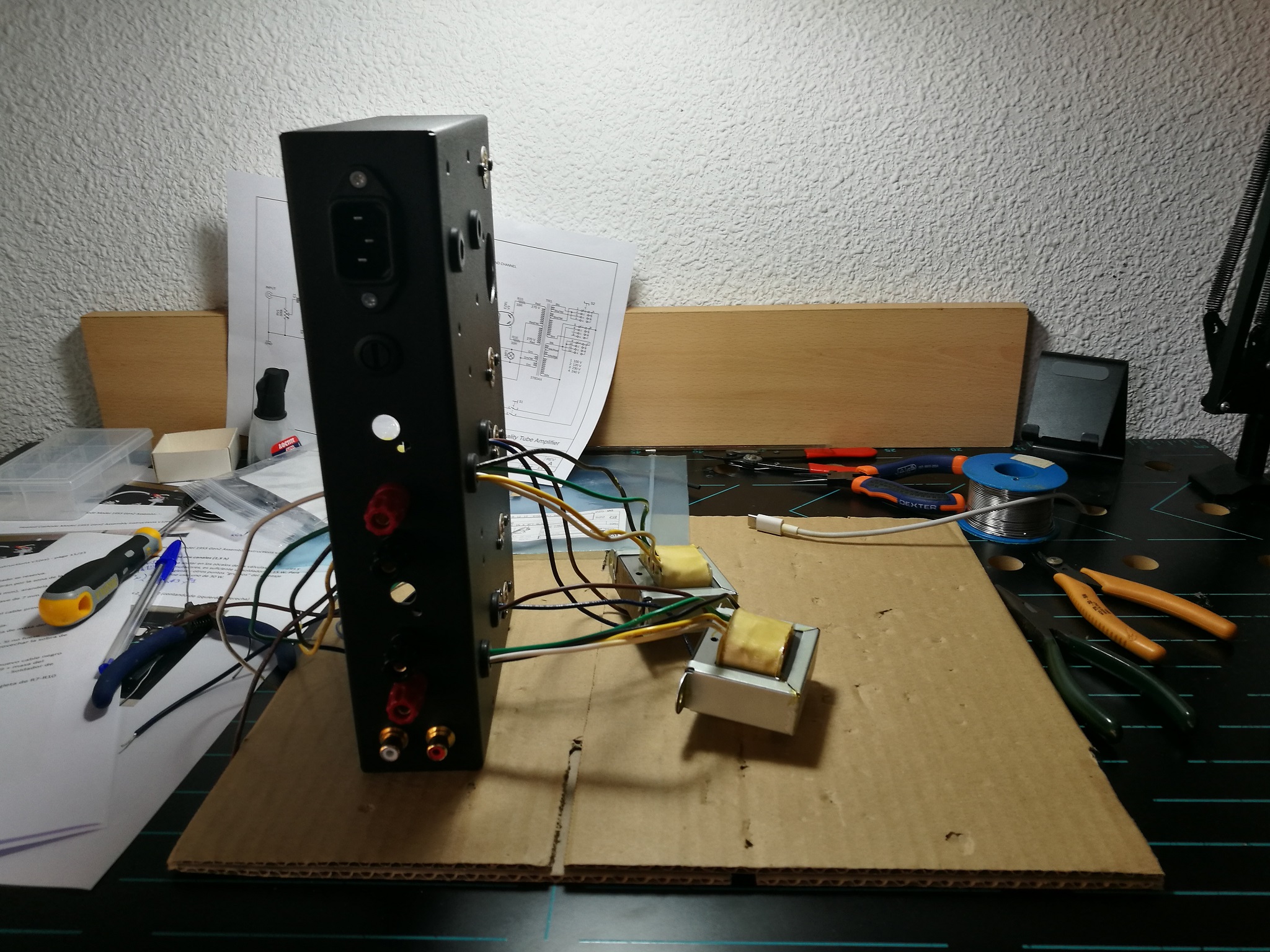
5. Mount audio transformers on both channels (2,0 h)
5.1.- Cut the orange wire flush with each transformer. The cut wire is reserved.
5.2.- Mount the transformers
- The brown and blue wires will come out of the grommet near the tube socket.
- Use M4 screws, split washer (Grower) and nut.
- Use a PH2 screwdriver and a 7 mm wrench.
Solder:
It is advisable to tin the end of the cables before soldering them.
5.3.- Brown wire to EL84 plate (7)
5.4.- White wire, and the rest of said wire after cutting it, to the terminal strips, pins # 4 and # 10.
5.5.- Black wire. The pins of the terminal strips # 5 and # 8 must reach (use 30W soldering iron):
- The black wire of the audio transformer.
- A new black wire to filter capacitor C6 + C9. (190 mm for the left channel)
- The masses of the input coaxial cables (sheathed in tube).
5.6.- Input coaxial signal cable, positions # 6 and # 7.
5.7.- Rest of orange wire, solder on the red speaker terminal.
5.8.- Solder two red wire for the positive of the power supply at the point of the terminals # 1 and # 11 so that it reaches the filter capacitor C6-C9.
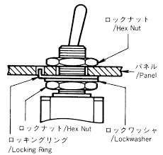
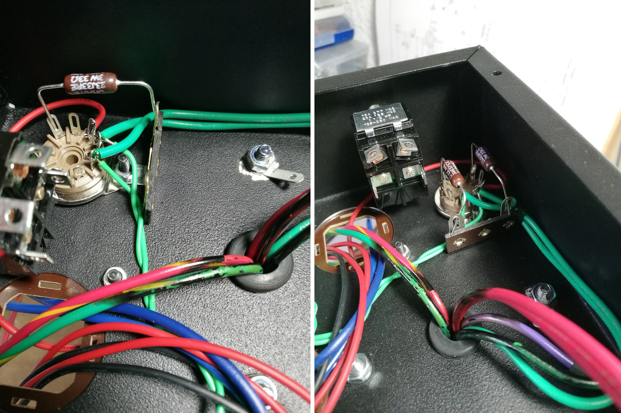
6. Mount impedance change switch (0,25 h)
6.1.- Mount the switch on the chassis
- 13 mm socket wrench
- Secure the plate with a bead of cyanoacrylate glue so that it does not rotate when tightening the switch nut. Protect the plate with absorbent kitchen paper while tightening it so as not to scratch it with the key.
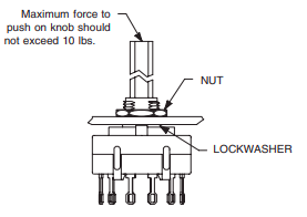
Install switch and lockwasher in back of panel. Tighten hex nut from front of panel.
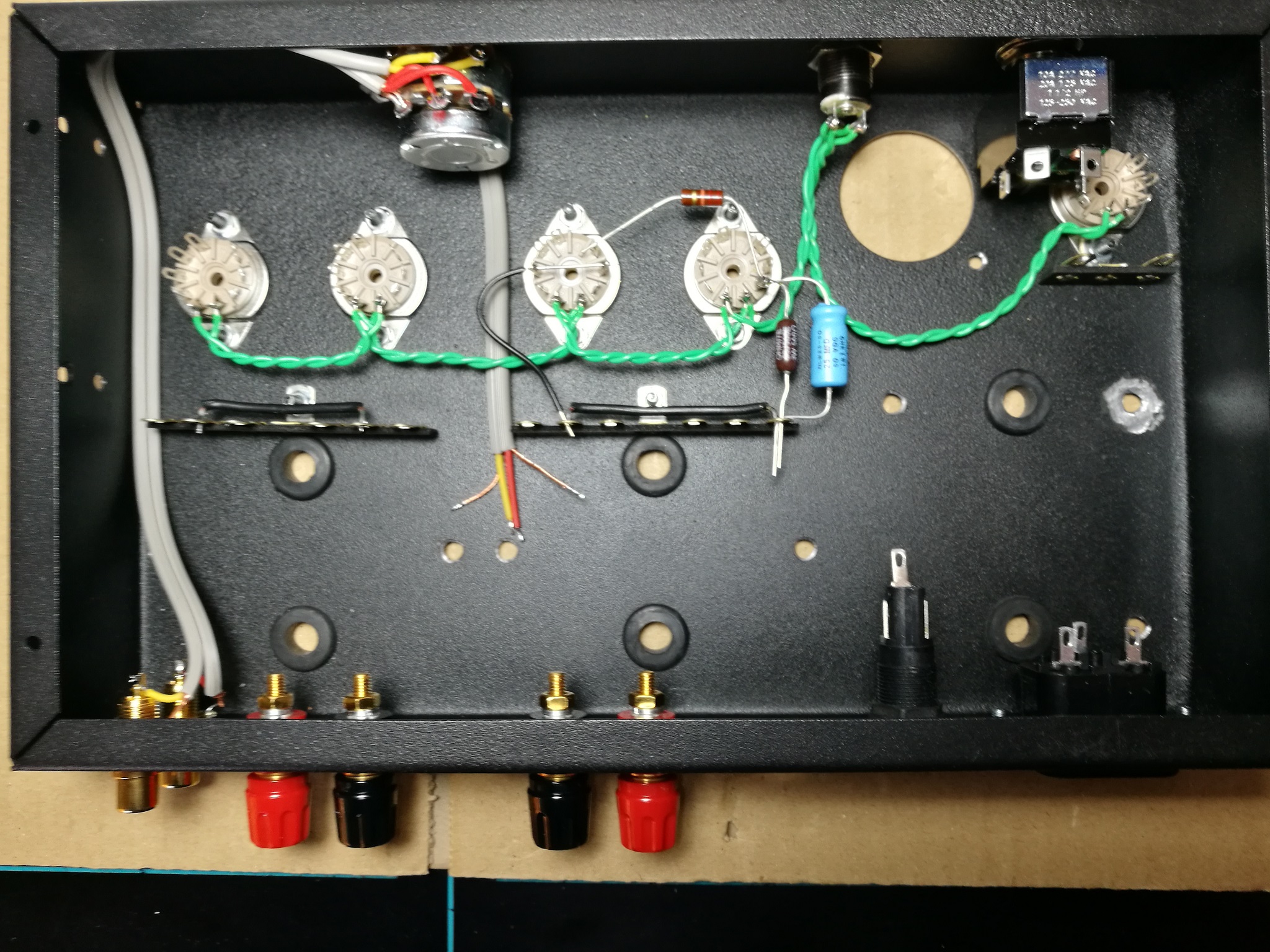
6.2.- Wire and solder at switch
7. Mount power transformer (1,0 h)
Is a good trick tinning the tip of the wires before solder it to the terminals.
7.1.- Mount the transformer
- The red, green and purple wires will come out of the grommet near the rectifier tube socket.
- Use M4 screws, split washer (Grower) and nut.
- Use a PH2 screwdriver and a 7 mm wrench.
7.2.- Do not forget the toothed washer on the top of the transformer leg that corresponds to the grounding point, nor the other toothed washer and the terminal before the nut below the chassis in the same transformer leg.
7.3.- (Check the ground connection between the transformer chassis and the ground of the audio input RCA connectors).
7.4.- Violet cable, cut 40 mm from the chassis and insulate it using 20 mm of heat shrink tubing.
7.5.- The green-yellow and red-yellow wires from the transformer should only go as far as filter capacitor C6-C9, cut to 100 mm. Using a remaining green-yellow wire from the transformer, connect the protective conductor (ground, ground) of the power connector (center pin) to the ground terminal of the transformer holding screw.
7.6.- Green wires, solder them to the filament circuit on the rectifier valve socket pins (4 and 5), cut to 130 mm.
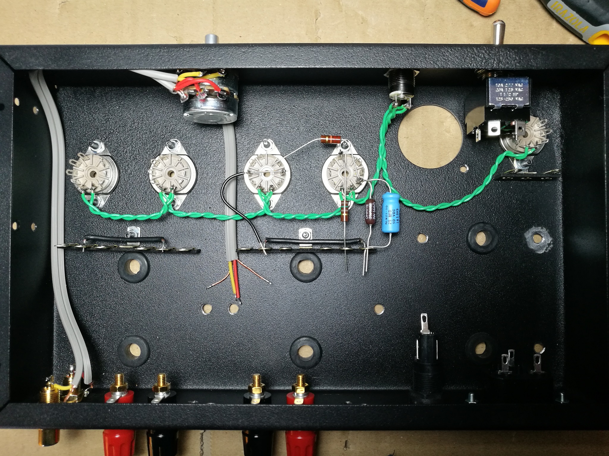
7.7.- Solder a red wire 110 mm on the cathode of the rectifier valve (3) that should reach the filter capacitor C6-C9.
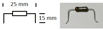
7.8.- Limiting resistors of the rectifier valve. Bend the legs so that 25 mm remains on the part that contains the resistor body, and then cut 15 mm from the bend. Solder the resistors in the valve socket (1 and 7).
7.9.- Red wires, solder them together with the resistor pins on the strip, cut to 130 mm.
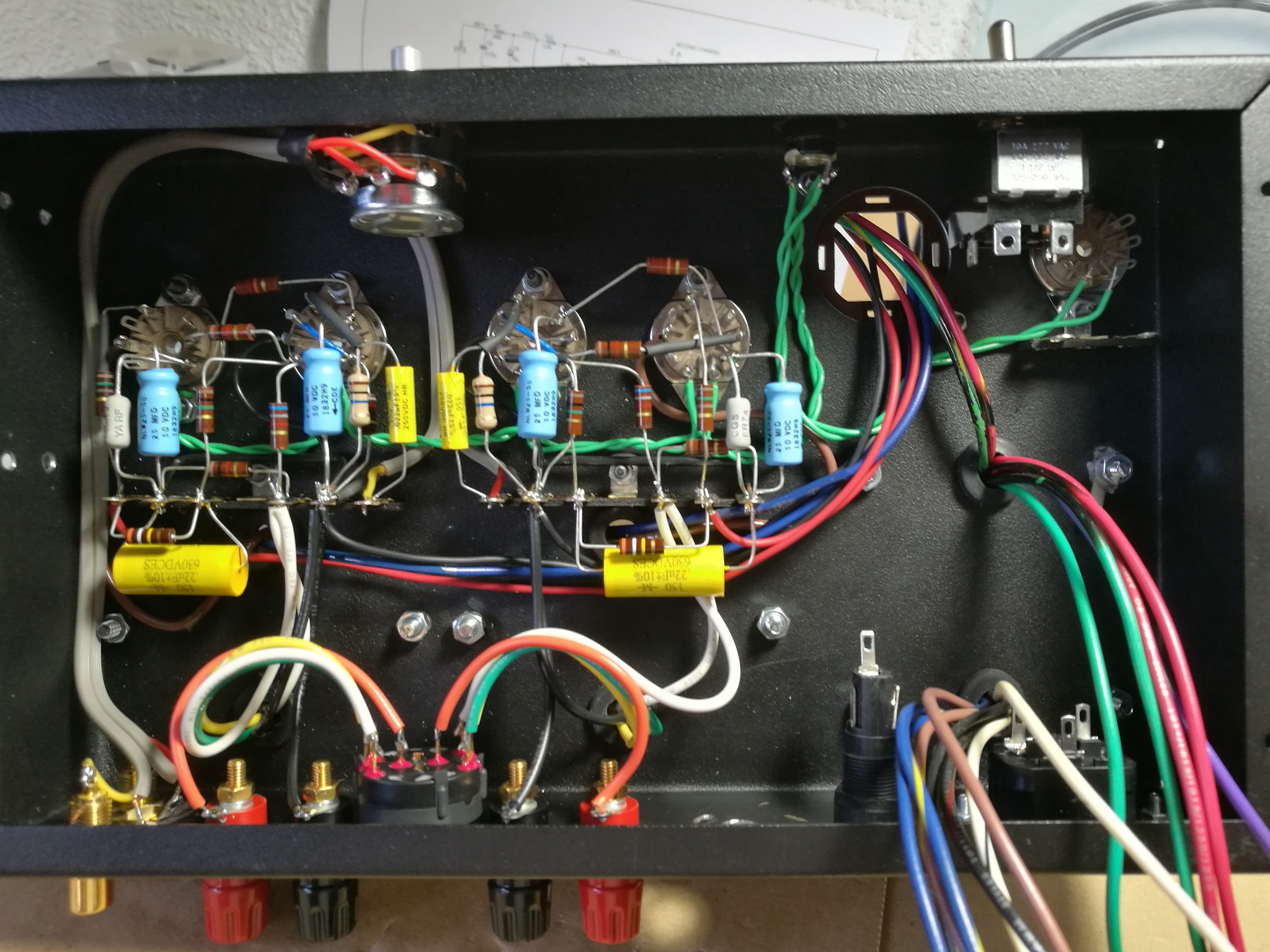
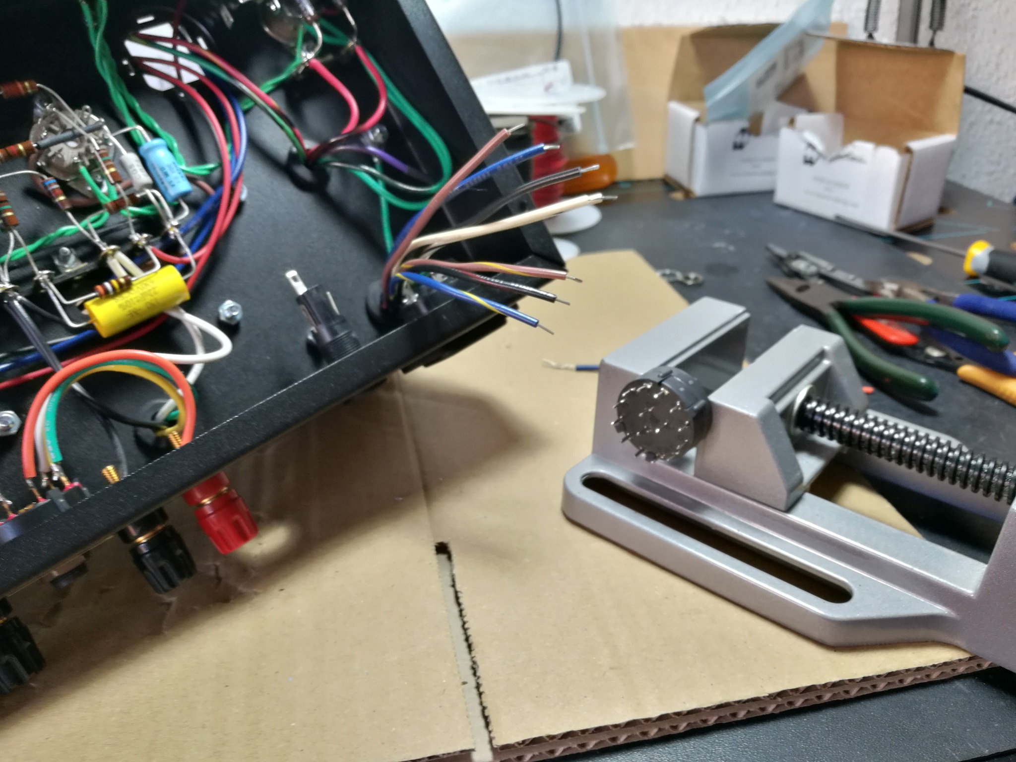
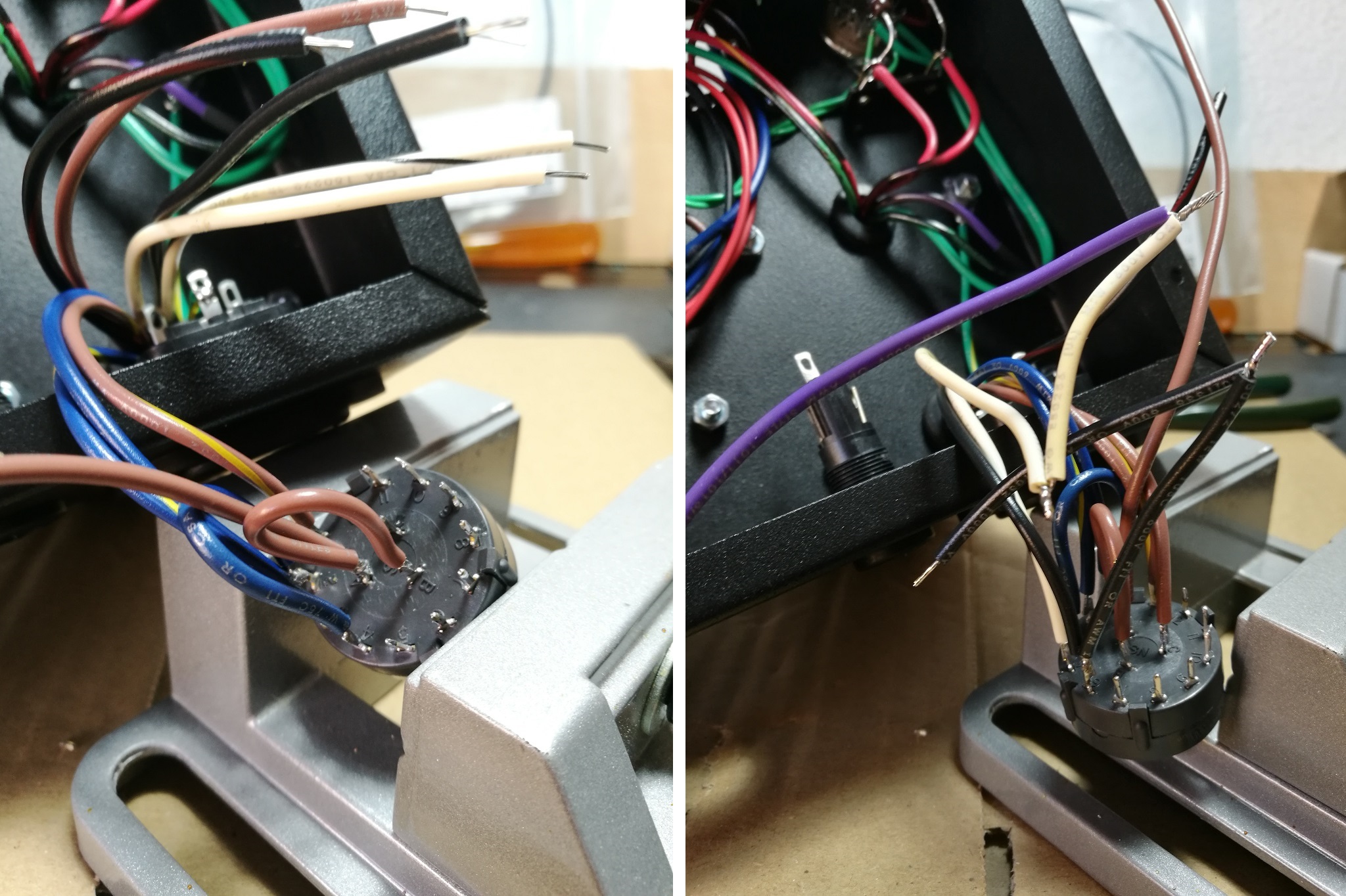
8. Assemble the voltage changer switch (1,2 h)
8.1.- Cut the cables coming out of the transformer to the following lengths
- black red 40 mm
- white 90 mm
- all blues 110 mm
- others 100 mm
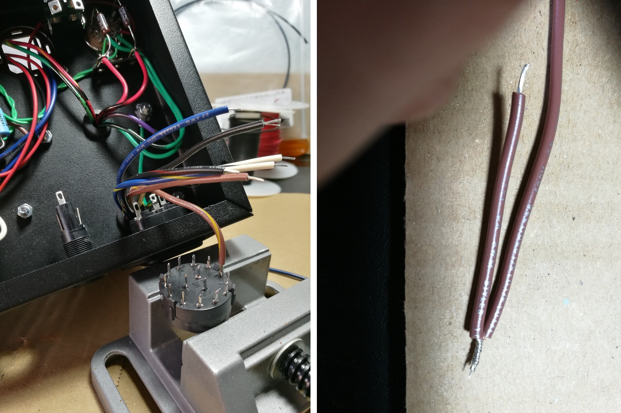
8.2.- Black-red cable, insulate it by 20 mm of heat shrink tubing.
8.3.- Strip (or peel) all remaining wires.
8.4.- Prepare segment wires in the following colours
- 1x blue (60 mm)
- 2x black (60 mm)
- 1x white (60 mm)
- 1x brown (60 mm)
- 1x brown (from changer to power switch, 200 mm)
- 1x blue (from changer to power switch, 200 mm)
8.5.- Tinning the switch pins.
8.6.- Wind (twiste) the segments with the cables of the same colour. Except for the brown one that has no transformer wire and the white one that ends with a blue wire.
8.7.- Tinning the tip of all wires.
8.8.- Solder on the changer switch, following the switch pins order: 1, 2, 3, 4.
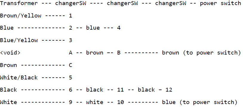
8.9.- After doing the 4, connect A-B-brown wire that reaches the power switch.
8.10.- Solder C.
8.11.- Continue in order: 5, 6, 7, …
8.12.- Don’t forget the neutral at 9, 10 with white wire, then use a blue (or purple) wire going all the way to the power switch.
8.13.- Mount the switch on the chassis (same as in section #6.- Mount impedance change switch).
9. Wiring switch and fuseholder (0,3 h)
Wiring switch, fuse and mains connector – Use brown and blue coloured cables.
- brown 80 mm
- brown 120 mm
- blue 120 mm
10. Mount filter capacitor (0,8 h)
10.1.- Mount the capacitor on its bakelite base by turning the tabs 90 ° with a pair of pliers. Hold the tabs by their end to do. Take a good look at the position of the capacitor terminals in the picture.
10.2.- Solder the two resistors R12 (2.2 k). Bend the legs so that 20 mm are on the part that contains the resistance body.
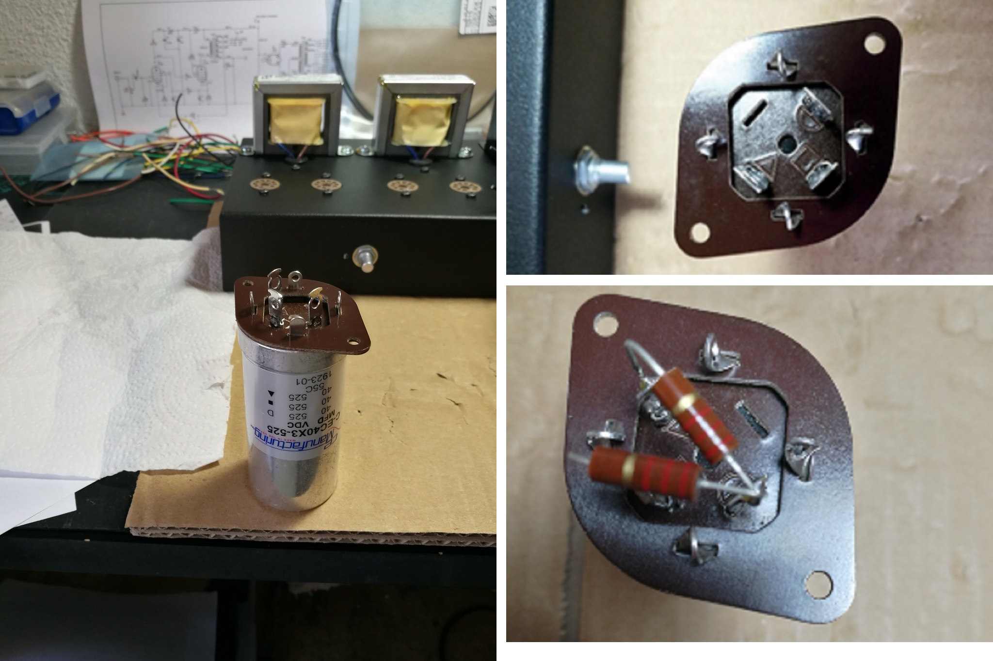
10.3.- Then fix the base to the chassis with black M3 screws, using two plain washers under the screw heads. Take a good look at the position of the capacitor terminals in the picture.
10.4.- Gather all the negative/ground cables and solder them on the negative capacitor pin.
10.5.- Solder the following three wires to C9, where the two resistors meet. The red one coming from the rectifier, and the two blue ones from the output transformers.
10.6.- Solder the red wires that come from the amplifier terminal strips to the two C6 250 and 100 mm.
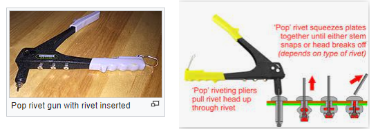
11. Mount Nameplate (10 minutes)
You can mount it with screws
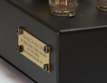
or with rivets (https://en.wikipedia.org/wiki/Rivet) using this tool
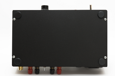
12. Chassis bottom cover
Stick the 4 rubber feet on the cover and use the screws to fasten it to the chassis.