When I first became interested in building a small vacuum-tube audio amplifier based on the Mullard 3-3 circuit, around the beginning of 2016, my original intention was to build it using point-to-point wiring, much like many vintage radio receivers.
The first Model 1955 amplifier was therefore conceived as a point-to-point wired project. Its initial chassis layout and wiring sketch later became the basis for the first prototype, now referred to as the 1955-1 tube amplifier.
I finally built that first prototype at the beginning of 2019, wiring the components point-to-point according to the original layout drawing documented on the 1955-1 wiring layout page. This first version confirmed that the amplifier could be built successfully in this way, but it also made clear that a printed circuit board could simplify assembly, improve repeatability, and make the project easier for other DIY builders to reproduce.
Originally written in January 2023, this article was last updated in June 2026.
Table of Contents
From Point-to-Point Wiring to a Printed Circuit Board
Years later, in 2021, I decided to design a printed circuit board for the amplifier as a recreational project.
I had previously used free PCB design software for other leisure projects, and I found the process relaxing and enjoyable. Designing the PCB also made the amplifier more accessible to others, especially to builders who might find point-to-point wiring more difficult or time-consuming.
With versatility in mind, I decided to design the printed circuit board as a single-channel PCB. Two PCBs are therefore used for the stereo amplifier, one for each channel. This approach also allows the same PCB to be used in mono equipment, such as radio receivers, record players, or other custom single-channel audio projects.
To be completely candid, I should also add that my use at the time of the free version of EAGLE, a CAD application for designing printed circuit boards, significantly influenced the decision to design two mono PCBs instead of a single stereo PCB, due to its 80 cm² board-area limitation.
Mirrored PCBs and Layout Considerations
In order to preserve the symmetrical layout of the amplifier, I later realized that two mirrored PCBs would be required.
Another design objective was flexibility. The PCB had to be suitable for use in any version of the Model 1955 amplifier, whether installed beneath a perforated chassis, as in the original Model 1955 layout, or mounted above a chassis or cabinet without tube cut-outs. This also makes the PCB easier to adapt to other custom audio projects.
To support these different mounting arrangements, the passive components, such as resistors and capacitors, are printed on both sides of the PCB. The wiring connection points are also printed on both sides, making the PCB easier to understand regardless of the mounting arrangement.
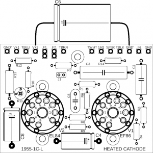
For installation in a Model 1955 chassis, each PCB is secured beneath the chassis using four 10 mm spacers, together with screws and nuts. The spacers use the existing noval tube-socket mounting holes, so the PCB can be fitted without drilling additional mounting holes in the chassis.
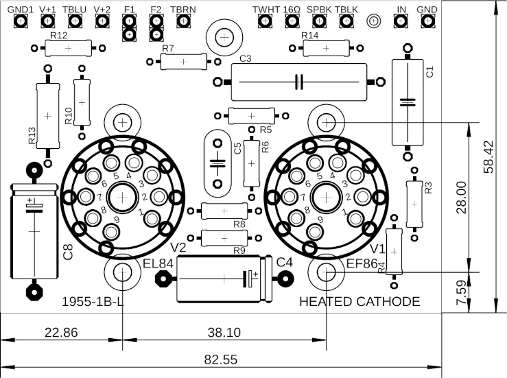
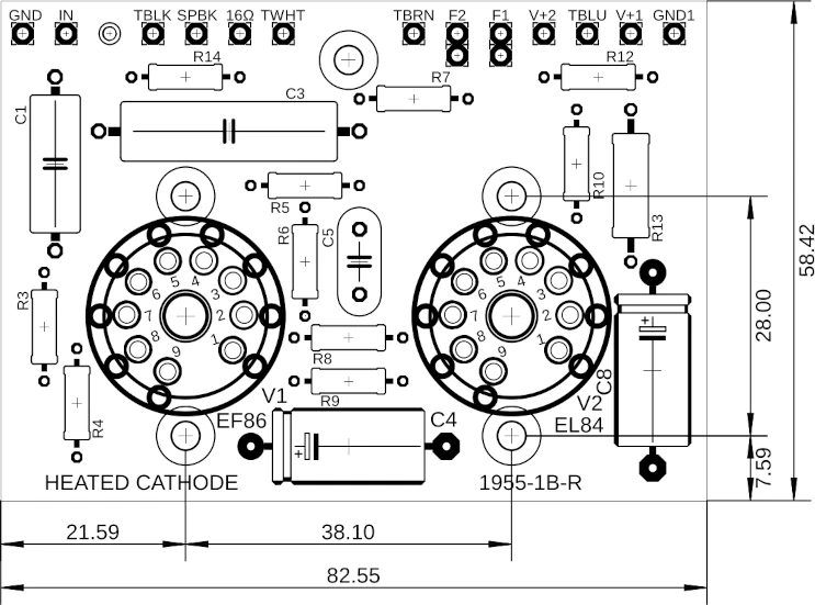
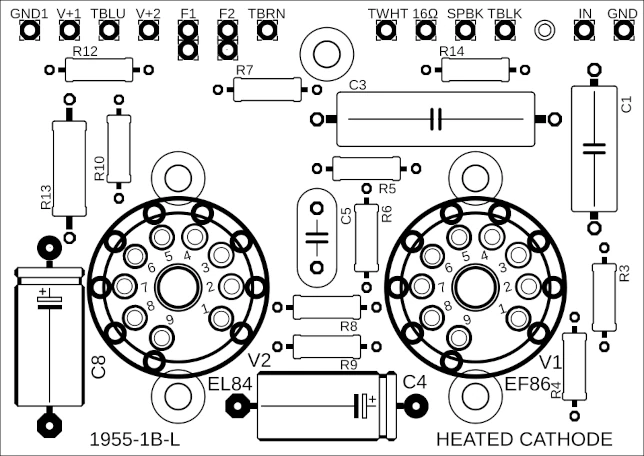
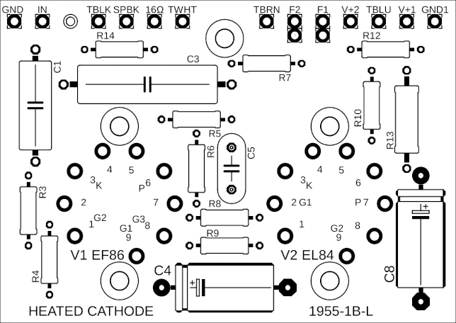
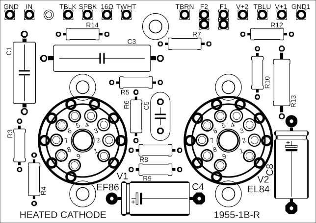
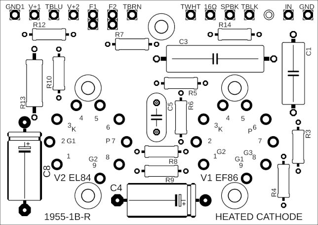
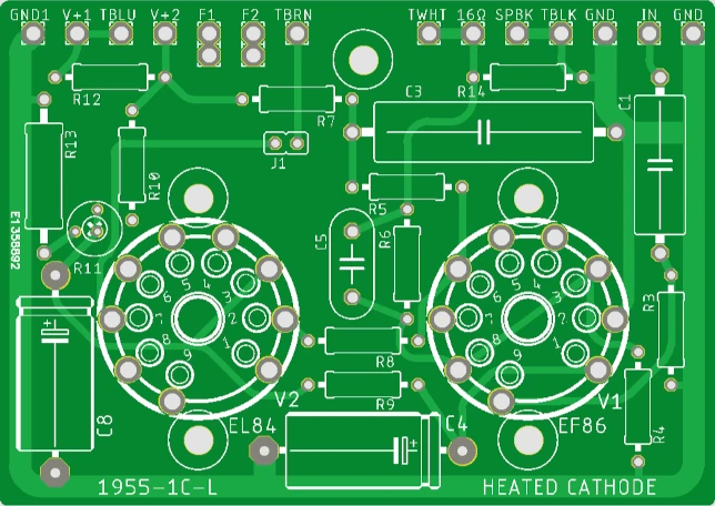
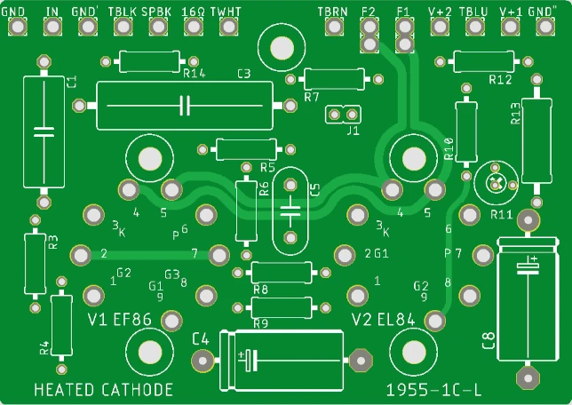
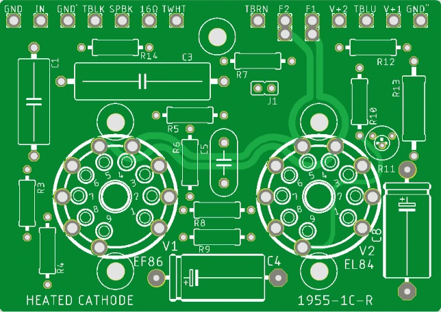
All PCB versions described in this article share the same overall dimensions: 82.6 mm × 58.4 mm (3.25 in × 2.30 in). The following dimensioned drawings show the left- and right-channel Version B PCBs.
All dimensions are in millimetres.
All dimensions are in millimetres.
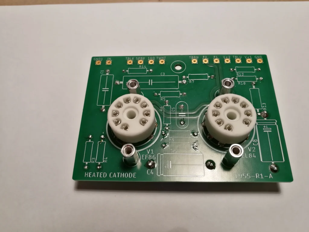
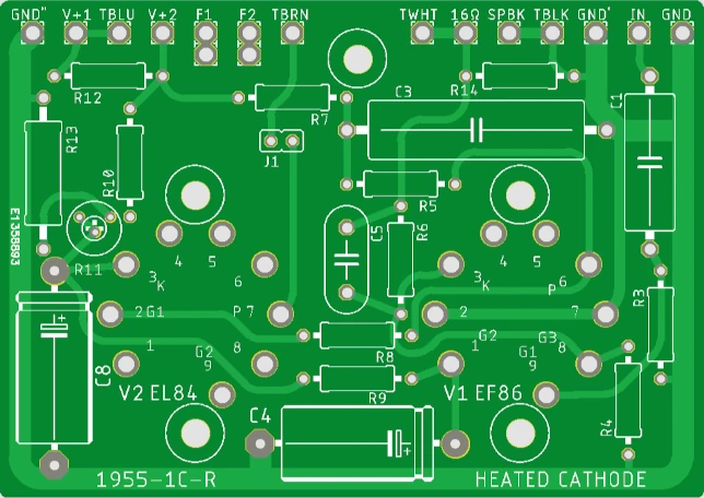
For tube sockets V1 and V2, I recommend using Belton VT9-PT PCB-mount noval sockets. These are 9-pin PCB-mount tube sockets with tinned phosphor-bronze terminals and a glass-fibre-filled PPS insulating body (Micalex). The PCB footprint was designed around this socket type, although equivalent PCB-mount noval sockets may also be used if their dimensions and pin arrangement are compatible. Some of the Version A PCB photographs show ceramic noval sockets fitted instead.
The printed circuit boards include the names of the vacuum-tube electrodes for the EL84 and EF86 tubes: cathode, plate, and grids. This makes it easier to identify the tube electrodes and measure the operating voltages while the chassis is open.
Warning: tube amplifiers contain potentially lethal voltages. Measurements inside the chassis should only be performed by qualified persons using appropriate safety precautions.
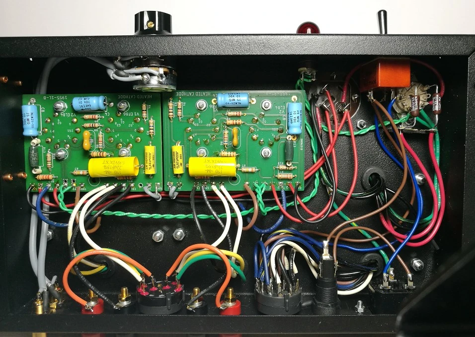
This underside view shows how the left- and right-channel PCBs are installed in the stereo amplifier. Each PCB carries one audio channel, and the mirrored arrangement helps preserve the symmetrical layout of the Model 1955 chassis. Mounting the PCBs beneath the perforated chassis also keeps the tubes visible from the top while leaving the components and wiring accessible from below during assembly, inspection, and testing.
PCB Versions
During the development of the Mullard 3-3 printed circuit board for the Model 1955 amplifier, several PCB versions were designed. The following notes summarize the main differences between Versions A, B, and C, and explain why some changes were introduced in later revisions.
Version A: Initial PCB
Version A was the first PCB version designed for the Mullard 3-3 amplifier stage. It was later superseded by Version B, mainly because the available space around the 3 W cathode resistor R13 was too limited for comfortable assembly.
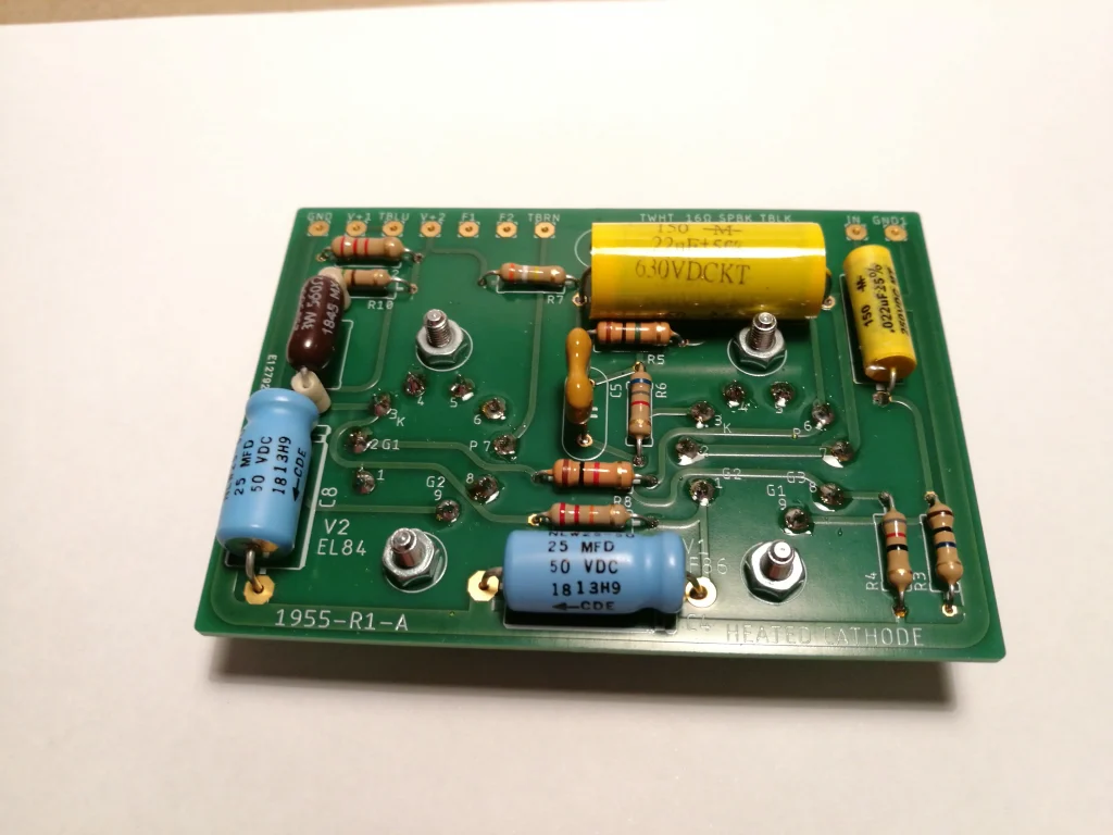
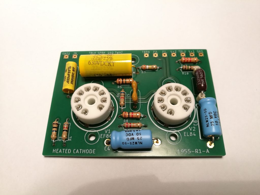
In the original component arrangement, the tube sockets were mounted on the top side of the PCB, while the passive components, such as resistors and capacitors, were mounted on the bottom side. This arrangement was intended for installation beneath a perforated chassis, as in the Model 1955 amplifier.
Although the PCB can physically be assembled with all components on the top side, this arrangement is not recommended for installation in a Model 1955 chassis. In that configuration, the components would be hidden between the chassis and the PCB, making inspection, servicing, and voltage measurements more difficult. In addition, the physical size of capacitor C3 prevents this mounting arrangement from fitting correctly beneath the Model 1955 chassis.
Version B: Revised Mirrored PCBs
Version B replaced the initial Version A PCB. The main mechanical improvement was the revised component placement around R13, providing more suitable space for the 3 W cathode resistor.
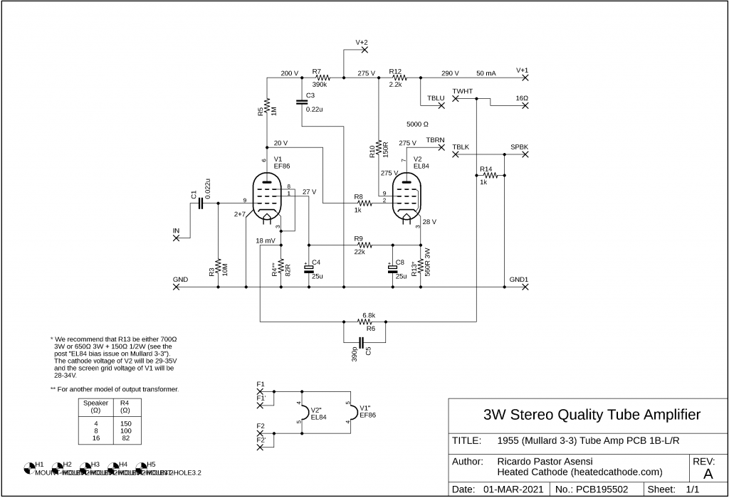
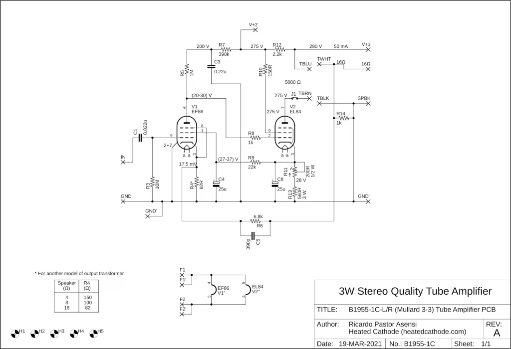
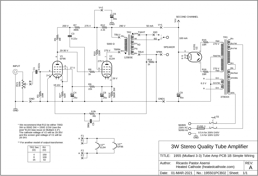
Download the B1955-1B PCB schematic (PDF)
The B1955-1B PCB was designed as two mirrored single-channel boards: B1955-1B-L for the left channel and B1955-1B-R for the right channel. This mirrored arrangement preserves the symmetrical layout of the Model 1955 amplifier while still allowing each channel to be assembled on a separate PCB.
The drawing below shows the top and bottom views of both the left- and right-channel Version B PCBs. The passive components, such as resistors and capacitors, are printed on both sides of the PCB, and the wiring connection points are also shown on both sides. This makes the PCB easier to read and wire regardless of whether it is mounted beneath a perforated chassis or adapted to another custom audio project.
Version C: EL84 Bias Adjustment and Plate-Current Measurement
Version C is based on the same general layout as Version B, but adds two useful features for setting the operating point of the EL84 output tube.
Download the B1955-1C PCB schematic (PDF)
The first addition is a 200 Ω adjustable resistor, R11, connected in series with the EL84 cathode resistor R13. This allows the cathode resistance to be adjusted and makes it possible to set the operating point of the output tube more accurately.
For adjustable resistor R11, I recommend using a Bourns 3329H-1-201LF trimmer potentiometer, or an equivalent 200 Ω, 0.5 W, single-turn cermet trimmer with the same footprint.
The second addition is a removable jumper, J1, placed in the EL84 plate-current path. When J1 is removed and a DC milliammeter is connected across its two pins, the EL84 plate current can be measured directly.
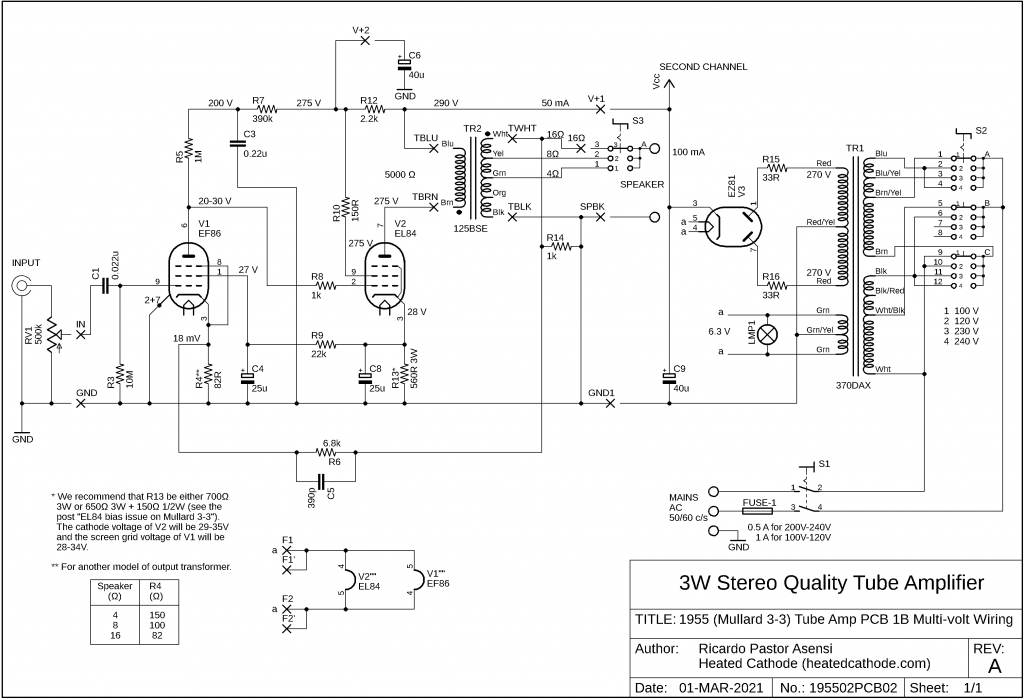
When these PCBs are used in audio equipment other than the Model 1955 amplifier, the can-type electrolytic filter capacitor C6 used in the Model 1955 power supply can be replaced by a modern 47 µF, 450 V axial aluminium electrolytic capacitor. This capacitor can be soldered directly to the PCB between the V+2 and GND connection points, as shown in the drawing below. Observe the correct capacitor polarity when installing it.
The Version C PCB therefore allows the EL84 operating point to be adjusted in either of two ways. The first method is to measure the voltage across cathode resistor R13, without removing jumper J1, and adjust R11 until the voltage reads 28 V. This corresponds to a cathode current of approximately 50 mA.
The second method is to remove jumper J1, connect a DC milliammeter across the two J1 pins, and adjust R11 until the meter reads 45 mA. In this case, the measured current is the EL84 plate current.
This circuit uses the ideas discussed in the article “EL84 bias issue on Mullard 3-3”, and practical tests with different EF86 tubes showed that the adjustment works well.
CAUTION: measuring the EL84 plate current
Tube amplifiers contain potentially lethal voltages. The following procedure should only be performed by qualified persons using appropriate safety precautions.
- Always disconnect the amplifier from the mains supply before removing or installing jumper J1.
- Never power the amplifier with J1 open unless a DC milliammeter is already connected across the two J1 pins in place of the jumper.
- Before switching the amplifier on, connect the multimeter, set to the 100 mA DC current range, across the two J1 pins using secure test hook clips.
- Always switch the amplifier off before disconnecting the multimeter.
- After removing the multimeter, reinstall jumper J1 before using the amplifier normally.
If the amplifier is powered with J1 open and no milliammeter connected, the EL84 plate circuit will be interrupted. In that condition, all the tube current flow through the screen grid instead, passing through screen-grid resistor R10. This cause R10 to overheat, smoke, and burn. This happened to me once during testing due to a bad connection in one of the milliammeter’s test leads.
Wiring Schematics
Download the 1955-1 amplifier wiring diagram for the B1955-1B PCB (PDF)
Download the 1955-2 amplifier wiring diagram for the B1955-1B PCB (PDF)
Implementing the Original Mullard Tone Controls
The original Mullard 3-3 amplifier included tone controls consisting of a treble cut and a bass boost. These controls are also used in the 1955-3 version of the amplifier.
If you wish to build the amplifier with the original tone controls, the schematic and reference images are available on the following page:
1955-3 The Mullard 3-3 with Original Tone Controls
The treble control can be wired according to the original amplifier schematic. The bass control, however, requires a small modification when using the Version A, B or C printed circuit boards.
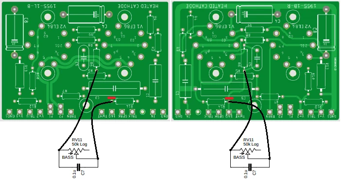
Bass Control Modification for Version B PCBs
To implement the bass control on the Version B B1955-1B PCBs, the track between the R6 and R14 connection points must be cut on each board. The cut is made on the top side of the left-channel PCB and on the bottom side of the right-channel PCB, as shown in the following images.
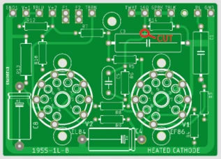
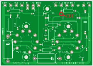
Use a sharp precision knife, such as an X-Acto knife. First, carefully scrape away the solder mask from the track. Then score the copper track several times until the cut is complete.
The best method is to cut through the track in two places and remove a small section of copper between the two cuts. This makes it easier to verify that the track has been fully interrupted.
Do not press too hard. Use several light passes instead of applying excessive force. This reduces the risk of breaking the blade or damaging the PCB.
Caution: always use a good-quality sharp knife and keep your fingers out of the cutting path.
For a visual reference on how to cut PCB tracks, watch the following YouTube video: https://youtu.be/qjI5SC3gboM?si=qsf7-sxSoXI9TdHl
Check the following points carefully:
- Confirm that the PCB tracks have been completely cut.
- Use a multimeter to verify that each cut track is fully open, and that no unintended shorts remain on the PCB.
- Check that no copper debris remains on the PCB.
Wiring the Bass Control
Once the tracks on both PCBs have been cut, the bass-control potentiometer must be wired between the R6 and R14 connection points on each channel.
Before powering the amplifier, check the following points carefully:
- Confirm that the bass-control wiring matches the schematic.
- Inspect all solder joints before applying power.
These small modifications allow the Version B printed circuit boards to be used with the original Mullard tone-control arrangement while retaining the advantages of the PCB layout.